Interfaces and
Buses/Gateway
Block Name: Gateway
Code File Location: VisualSim/actor/arch/Gateway/Gateway
Description
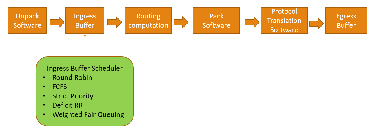
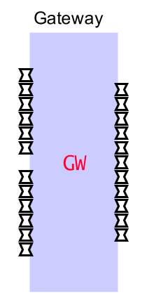
This module represents a generic automotive Gateway module. This module is built with various configurable parameters which will help user to easily map the settings of a target automotive Gateway. By default, the Gateway provides 23 interfaces to the user. This means, 23 connections can be made to this switch from other masters, networks, ECUs, TSN_Switches, Slaves, Sinks etc.. If more than 23 interfaces are required, then the additional interfaces can be instantiated as per users requirement.
Block Diagram respresentation of the Gateway:

VisualSim Gateway module :

Use the following links to access existing demo models:
Simple Demo model - This demo model has a Gateway module and CAN_Bus networks.
TSN_Switch+GW+Datacentre - This demo model has TSN_Switch, Gateway, CAN Bus, Datacentre, workload generators
Required blocks
For the user to
simulate models using Gateway, user must instantiate Gateway_Config_DB (Location : Interfaces and Buses -> Gateway)If user want to connect any modules other than TSN_Switch or CAN_Bus, then user must use Gateway_Interface_Unit. Please refer to this demo in order to view how Gateway_Interface_Unit is being used.
Required input Data structure fields
Use the Data Structure template defined by the name "Task_Class". Along with the fields defined within "Task_Class", add the following:| Data
Structure Field Name |
Description |
Value
(Examples) |
| Task_Size |
Size
of the packet in bytes |
1512 |
| Message |
Used
to define the message value, It will be used while doing packing operation. |
"ETH_Transfer" |
| Hash_Id |
Unique Identifier. It will be used while doing Forwarding Table lookup. | "0x102" |
Blocks which can be connected to the Gateway
We must use Gateway_Interface_Unit when connecting a module to the Gateway. There are few components which dont require it for establishing connection. They are TSN_Switch and CAN_Bus.As long as the incoming data structure contains all the required inputs as specified above, it will work well. Else, an exception will be thrown.
TSN_Switch can be connected to the Gateway module directly to any one of the ports.
Worloads which generate frames in the required data structure format can be connected to Gateway_Interface_Unit which inturn is connected to the Gateway module.
Parameters
| Parameter
Name |
Description |
Example
Value |
| GW_Name |
Unique
name for the Gateway |
"GW1" |
| Gateway_Speed_Mhz |
Gateway speed in Mhz |
1000.0 |
| Ingress_Buffer_Size |
It
is the maximum number of frames which can be stored in the Ingress
buffer. When a frame comes in, they are stored in the corresponding
ingress buffer until scheduler scheduled the required resources for the
frame. If the number of incoming frames go above this value, then they
are dropped. |
1000 |
| Egress_Buffer_Size |
It
is the maximum number of frames that can be stored in the Igress
buffer. When a frame reaches the destination port of the gateway, they
are sent out one by one. So if large number of frames are being sent
out via the same port causing the number of frames to go higher than
this value, then the excess frames are dropped. |
1000 |
| Scan_Rate | Scheduler
scans for next frame at this period. It is in Seconds. So every
Scan_Rate seconds, the scheduler scans for a new frame. |
1.0e-6 (this mean 1 usec) |
| Sw_Details |
This parameter lists out the software details and their execution latency (in clock cycles) in a table format. |
Sw_Name Proc_Cycles ; Routing_Sw 250 ; Packing_Sw 200 ; UnPacking_Sw 200 ; Security_Sw 350 ; |
| View_Stats | Set it to be true if the stats across Gateway needs to be viewed |
true |