
| Data Structure Field | Description | Value (Examples) |
| A_Source | Source or Root Complex device name | Source |
| A_Destination | Destination or End Point device name | Destination |
| A_Hop | Transaction flow path towards destination | A_Destination |
| A_Command | “Read” or “Write” operation | Write or Read operation |
| A_Bytes | Number of data Bytes for this transaction | 1024 |
| Parameter |
Explanation | Example |
| Architecture_Name | “Architecture_1” (String) | Name of the Architecture_Setup block |
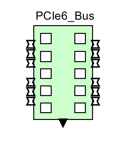
| PCIe_Switch_Name | “PCIe6_Switch” (String) | Unique name for this Bus. Different from all architecture blocks and global model memories. |
| Max_Read_Req_Size_Bytes | 4096 (int) (bytes) | This
is the max Request size for a packet that can be recieved at any
Endpoint ports of the switch. If it is greater than the value specified here, then an error is thrown. |
| Flit_Size_Bytes | 256 (int) | Flit_Size is the fixed size in Bytes which is used to define the packet size when sending the packet from sender to receiver ports. |
| Number of Lanes | 16(int) | 1,2,4,16,32,
and 64 are the only possible values. The user is restricted
to
these values only. This can be a single value or an array of the Number of Master. |
| Buffer_Size_Bytes | {4096,4096} //RX,TX | Number
of Bytes irrespective of the number of transactions for Rx and Tx. |
| Overhead_Cycles | 0 (int) | For Each frame - EndPoint Rx Buffer to Crossbar and Crossbar to EndPoint Tx Buffer, Overhead_Cycles will be added to the total delay cycles. |
| Devices_Attached_to_Ports | {{"Dev_1"},{"Dev_2"},{"Dev_3"},{"Dev_4"},{"Dev_5"},{"Dev_6"}, {"Dev_7"},{"Dev_8"},{"Dev_9"},{"Dev_10"},{"Dev_11"},{"Dev_12"}} |
This is a 2-D array which the user can use to specify the device names of the devices attached to each EndPoint. It the connected Device has the capability to send the Hello Message, then user shouldnt worry about updating this array as it will be updated automatically once it receives the hello message. |
| Enable_Debug | true (boolean) | Set
it to true and connect a TextDisplay to the Debug_Port (south side of
the Switch) to view all the sequences happening within the PCIe_Switch. |
| BER | 1.0E-11 (double) | Range
is 0.0 to 1.0. During CRC check, a random number is
generated. If the number is below this BER, a Nack is
returned. If above, the transaction is accepted. |
| NumberOfRetry |
4 (int) |
If
the transfer gets failed due to CRC Check sum failure, then it would be
retransmitted. But if the same frame gets failed continuously, then it
cannot go above the NumOfRetry value. If it goes above the NumOfRetry
value, then the transaction is dropped at the PCIe6_Switch. |
| Timeout | 6E-6 (double) | Timeout specifies the amount of time to wait for an acknowledegment to arrive for a FLIT that was transmitted prior. If the Ack is not received within the Timeout expires, then the corresponding FLIT is retransmitted. |
| Enable_Master_Flow_Control | false (boolean) | Set this parameter to be true if Flow Control needs to be enabled between the transaction initiator and the PCIe6_Bus. Setting this parameter would mean that All EndPoints are now operating under the effect of Flow Control (Meaning that the incoming Data Structure must contain "Event_Name" field). User can add a field called "Master_Flow_Control_Enable" and set it to be false if the connected EndPoint doesnt wish to have Flow Control Enabled. |
| Enable_Slave_Flow_Control | false (boolean) | Set this parameter to be true if Flow Control needs to be enabled between the PCIe6_Bus and Destination EndPoint. Setting this parameter would mean that All EndPoints are now operating under the effect of Flow Control (Meaning that the PCIe6_Bus would wait for the Event to be generated so that it can send the next packet out to the connected EndPoint). User can add a field called "Slave_Flow_Control_Enable" and set it to be false if the destination EndPoint doesnt support Flow Control. |
| Replay_Buffer_Size_Bytes | 1024 |
Store a copy of all Transmitted TLPs until the remote receiver acknowledges them. |
| Number_Of_Successive_Acks | 3 | Number of Successive Acks used by Selective naks provided Selective Aak is supported. PCIe6 supports Selective Nak on top of classical Nak. With Selective Nak, just a selective FLIT can alone be retransmitted there by saving bandwidth. For this to happen, "n" number of consecutive Naks should be received at the sender . Then the sender identifies it as a retransmission request and retransmits the FLIT. ("n" is the value set for this parameter). For Classical Nak, it request for a group of FLITS to be retransmitted. Often happens when FLITS are received in out of order or a FLIT in between found to be missing etc.. |
| Enable_Selective_Ack | true | Setting value true would enable Selective Ack feature on top of Classical Ack.With Selective Nak, just a selective FLIT can alone be retransmitted there by saving bandwidth. For this to happen, "n" number of consecutive Naks should be received at the sender . Then the sender identifies it as a retransmission request and retransmits the FLIT. ("n" is the value set by Number_Of_Successive_Acks). For Classical Nak, it request for a group of FLITS to be retransmitted. Often happens when FLITS are received in out of order or a FLIT in between found to be missing etc.. |
| Enable_Hello_Msg_Forwarding | true | In
VisualSim, All connected devices send a message called "Hello_Message"
at startup. This is to make sure that the Buses, interconnects, bridges
know where each of the devices are located. Enable this parameter to
forward the hello message received on one port to all other ports. In a
big network, enabling it would be helpful (provided there are no bus
connections in loop). |