Creating a System Model
Tutorial Goals
- Use the hardware blocks to develop a system model.
- Combine traffic generators and processing blocks to define the transaction rate and content.
- Evaluate the performance of bus and DMA.
- Examine the overhead of an external or off-chip DRAM.
Model Location
Open this model in VisualSim from the following location:
$VS/doc/Training_Material/Architecture/Tutorial/Architecture_Exploration/Using_DMA/
Model Introduction
This model demonstrates the
use of the Hardware Architecture Library in VisualSim. The session
combines the performance and architecture libraries in assembling a
detailed system model. This session helps you understand how to
connect and configure the blocks into a model.
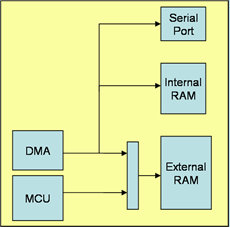
Figure 1: Block Diagram of the System Architecture Model
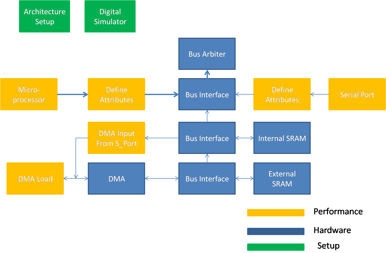
Figure 2: VisualSim model of the System Architecture
List of Block Used
Sl No
|
Library Block
|
Description
|
1
|
Digital Simulator

ModelSetup > Digital
|
This
Simulator is used to model protocols, hardware, and mapping of behavior
to architecture. This simulator is used when the model is being
triggered as an event or based on time. The Digital Simulator
implements the discrete-event Model of Computation (MoC). This
Simulator maintains a notion of current time, and processes events
chronologically in this time.
|
2
|
Traffic

Traffic > Traffic
|
Traffic
block outputs a new Data Structure (DS) at time intervals specified by
the "Time_Distribution" setting. A Data Structure is a transaction
containing a list of Field Names + Values.
|
3
|
Expression_LIst

Behavior > Expression List
|
The
Decision/Expression_List blocks execute a sequence of expressions in
order. The default block contains one input and one output. The user
can add multiple input and output ports.
|
4
|
Text Display

Result > Text > Text_Display
|
Displays
the values arriving on the input port in a text display dialog. This
block buffers the display data and updates the screen after the buffer
is full.
|
5
|
TimeDataPlotter

Results > TimeDataPlotter
|
This
block plots the incoming data on the Y-Axis against the current
simulation time on the X-axis. Every wire connected to this block input
is considered a separate dataset and plotted separately.
|
6
|
Architecture Setup

Hardware_Setup > Architecture_Setup
|
This block handles all the address mapping, routing, plotting, statistics and debugging for the Hardware Modeling components.
|
7
|
DMA

Hardware_Devices > DMADatabase
|
DMA block that represents a memory controller that sits between the Processor or bus or I_O Block and the Memory bank.
|
8
|
RAM

Memory > RAM
|
This
block combines the operation of a basic memory controller (delay
function) and the memory array. The block handles pre-fetch, read,
write, refresh, and controller operations. The block can be interfaced
to any Bus or Memory Controller.
|
9
|
Delay

Traffic > Delay
|
This block delays the incoming Data Structure by the value specified in the Delay Parameter.
|
10
|
Parameter

Model > Parameter >Parameter=
|
Parameter is a variable containing a constant that can be any VisualSim data type, function and/or a RegEx expression.
|
11
|
Initialize

Full Library > Source > Event > Initialize
|
This
block can be used to generate a value at the start of a simulation at a
zero delay. User can set an Initial Order, 0 being the lowest priority
and higher values fire before lower priority Initialize blocks.
|
12
|
Statement

Full Library > Defining Flow > Basic Processing > Statement
|
This
is a block that executes a mathematical expression on each of the four
Field_Statement lines based on the Data Structure Expression language.
|
13
|
If_Else

Full Library > Defining Flow > Basic Processing > If_Else
|
This
is a programming if-else operation. If the condition in the
"If_Statement" equates to a true or 1, then the line numbers listed in
the "if_Execute" are executed.
|
14
|
Variable List

ModelSetup > Variable List
|
The
block is used to define memory locations that can be used
in Expression, Decision, Basic Processing (Statement etc.),
Smart_Machine, and Virtual_Machine blocks.
|
15
|
BusArbiter

Hardware Devices > BusArbiter
|
The
Linear_Bus or Bus Arbiter block is the Arbiter for a Linear Bus or Bus
Interface. The Linear bus is a shared bus topology with an arbiter.
|
16
|
BusInterface

Hardware Device > Bus_Interface
|
The
Linear_Port or Bus Interface block is used to connect the devices to
the Linear_Controller Bus. The block has a queue for each
port. The incoming transactions are queued and the head of the queue is
sent to the Controller Queue.
|
17
|
IN

Behavior > IN
|
This
block accepts incoming Data Structures or tokens from any
OUT/MUX/uEngine/Virtual_Machine blocks and sends a value on the output
port. The single parameter called Destination_Name is composed of two
parts - the name and the value to be output, separated by ".".
|
18
|
OUT

Behavior > OUT
|
The
OUT block accepts Data Structures or tokens arriving in the input port
and transmits them as a virtual connections to IN, MUX, NODE, Virtual
Machine, and uEngine.
|
- ModelSetup > Digital
- Traffic > Traffic
- Behavior > ExpressionList
- Results > Text_Display
- Results > TimeDataPlotter
- Hardware_Setup > Architecture_Setup
- Hardware_Devices > DMA
- Memory > RAM
- Traffic > Delay
- ModelSetup > Parameter=
- Full Library > Source > Event > Initialize
- Full Library > Defining Flow > Basic Processing > Statement
- Full Library > Defining Flow > Basic Processing > If_Else
- ModeSetup > VariableList
- Hardware Devices > BusArbiter
- Hardware Devices > BusInterface
- Behavior > IN
- Behavior > OUT
Model Details
The system uses the following
blocks: DMA engine, serial port, internal memory, external memory,
fixed priority arbiter, and a processor core (traffic generator). See the following figure for more details.
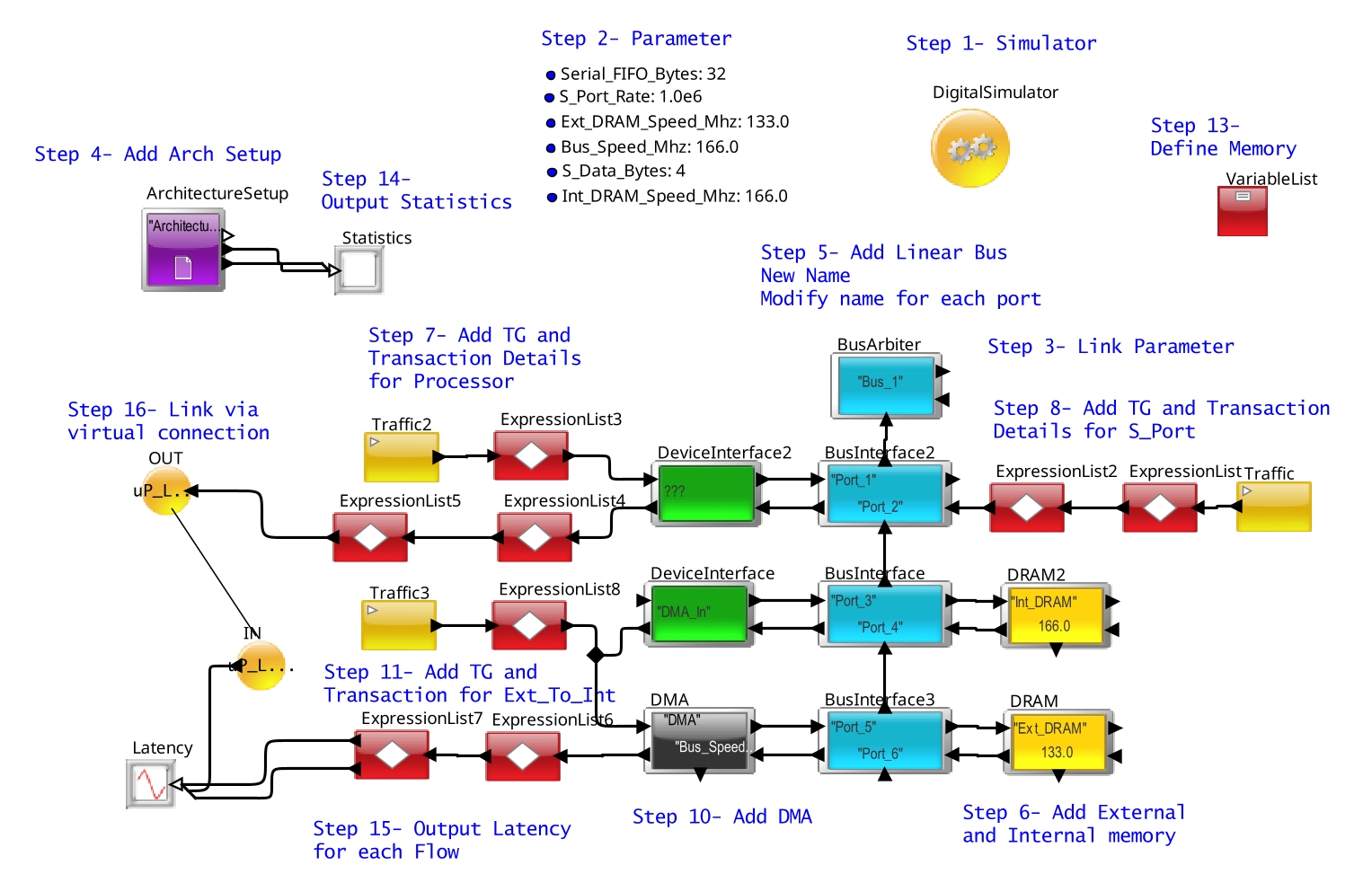
Figure 3. System Architecture Model
There are three data flows:
- One DMA channel moving from external to internal memory.
- One DMA channel moving from the serial port to internal memory.
- Processor reading from external memory.
DMA
- Processes bursts (8 reads, then 8 writes)
- Configurable overhead cycles per burst
- 2 logical channels
- Only 1 bus interface
- Higher priority channel can interrupt the lower priority channel between bursts only
Device Interface
- Use Device Interface block to define the name of the source
Serial Port
- Configurable FIFO depth and configurable frequency of receiving data.
- Trigger the DMA when the FIFO reaches a certain depth.
Memory
- Internal and external memory need configurable latency.
- Initial access has different access from subsequent beats of a burst.
Processor
- Generates random accesses in bursts of 32 Bytes.
Bus
- 32 bits wide
- 32 bytes are transferred in one burst
Other Details:
- A transfer as a read and a write.
- To move data from external memory to internal memory, the DMA reads from external memory and writes to internal memory.
- Likewise, to move data from
the serial port to internal memory, DMA reads from the serial port fifo
and writes to internal memory.
- The higher priority channel is the serial port channel. The lower priority channel is the external memory channel.
Step-by-Step Instructions
- Instantiate the Digital Simulator block. Select the digitalDomainOnly option to use the high-speed version.
- Add parameters. In
this case, the parameters are the Simulation Time; Serial port
frequency and FIFO depth; SRAM, DRAM and Bus speed; and Serial Data
Bytes size.
Sim_Time
:
100.0E-6
Serial_FIFO_Bytes : 32
S_Port_Rate
:
1.0E6
Ext_DRAM_Speed_Mhz : 133.0
Int_DRAM_Speed_Mhz : 166.0
Bus_Speed_Mhz : 166.0
S_Data_Bytes
: 4
- Link the Simulation Time with the Digital Simulator stopTime.
- Instantiate the Architecture_Setup block.
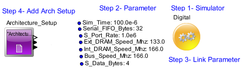
Figure 4. Arch_Setup
- Instantiate a
Linear Controller or BusArbiter and 3 Bus Interface / Linear Port
blocks below them. Configure it as shown in the figure below:
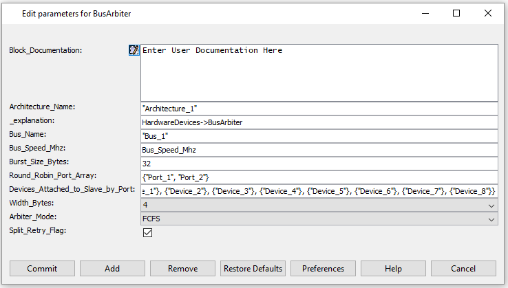
Figure 5. Linear_Bus
- Instantiate the External and Internal Memory (RAM blocks for both).
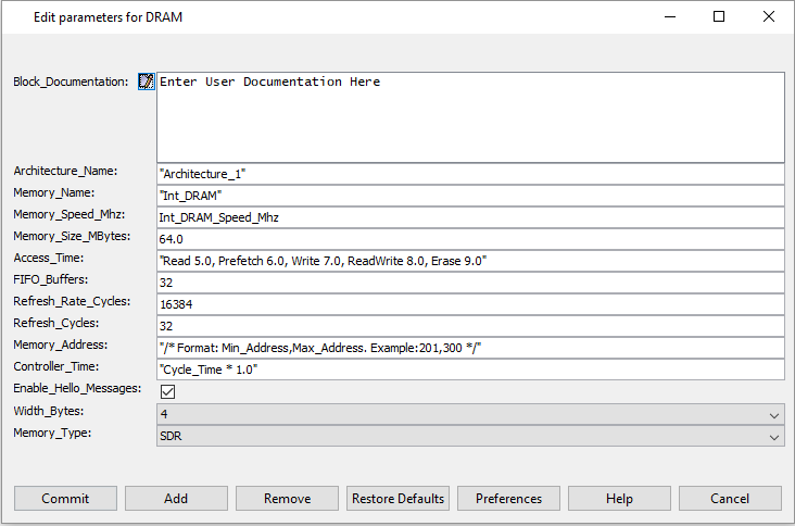
Figure 6. DRAM_Config
- Create an ExpressionList block and
populate it as shown below. In this tutorial we are using field names
to provide DMA parameters, these can be seen in the image below.

Figure 7. Parameters for Statement
- Use Device Interface to specify the source name as "Processor".
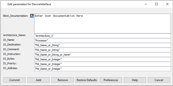
Figure 8. Parameters for Device Interface
- Connect them to the
Bus Interface.
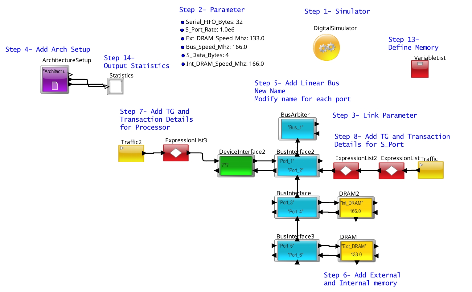
Figure 9. Before adding DMA
- Next instantiate and configure the DMA.

Figure 10. Parameters for DMA Controller
- Instantiate a DeviceInterface block. Specify the source name as DMA_In.
Figure 11. Parameters for Database Block
- Instantiate the
Traffic and the ExpressionList block to define the attributes to generate
the transactions for the Ext_to_Int transfer.

Figure 12. DMA_Next
- Initialize a memory to store the current FIFO depth for the Serial Port.
- Attach a
Text_Display block to the stats and util output of the
Architecture_Setup block. Also, configure the Trigger input to the
DMA for returning the acknowledge message.
- Connect the two DMA flows and the Processor flows to the Latency processing and TimeDataPlotter for displaying the Latency.
Figure 13. Full SRC
- Use the OUT + IN block to connect the Processor output to the Latency plotter.
Execution
- Click on the "GO" button to start the simulation.
- Make sure you get an output on the Text_Display.
Experiments
Now that we have run the basic model we can start experimenting with it
by changing various parameters and observing the differences in the
latency plot. The following is a list of some variables we will be
changing essentially one by one.
1. Outstanding_Req_Count in DMA Controller
2. Data Size from transaction field in ExpressionList2 & ExpressionList8
3. Burst Size from transaction field in ExpressionList2 & ExpressionList8
4. Width_Bytes from transaction field in ExpressionList2 & ExpressionList8
5. Number of Channels and distribution of traffic in DMA Channel and ExpressionList2 & ExpressionList8
We will first establish a baseline for this we will use the following:
Outstanding_Req_Count: {1,1}
Data Size: 32
Burst Size: 32
Width_Bytes: 4
Number of Channels 1
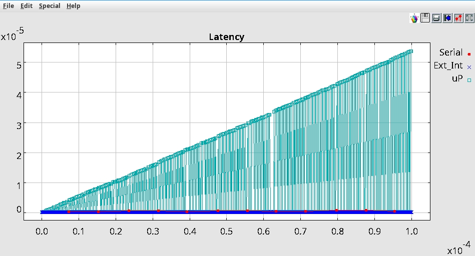
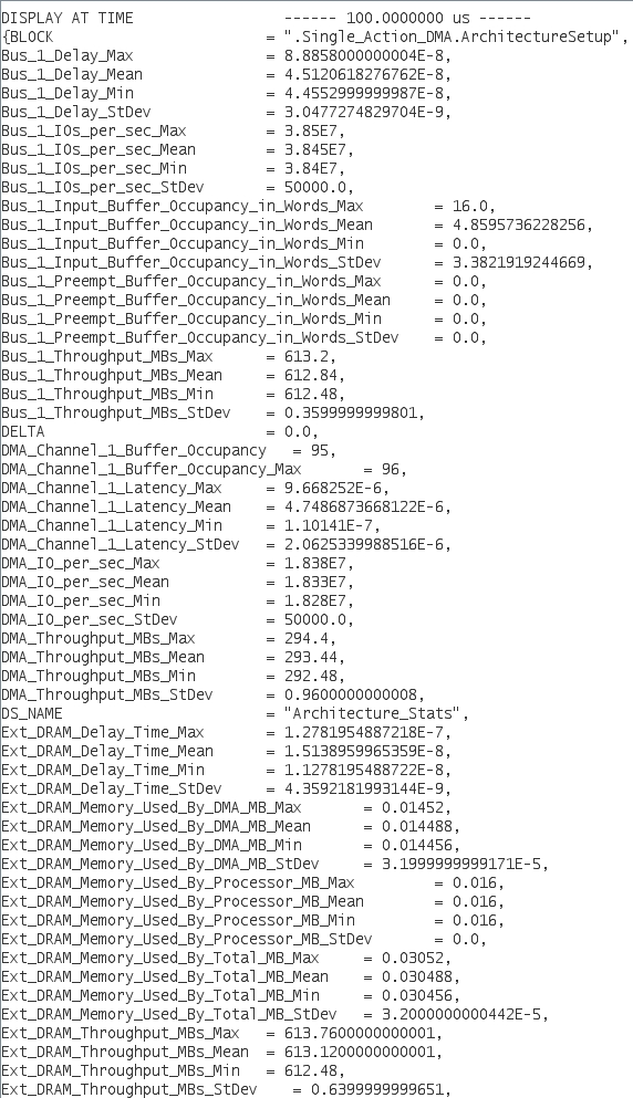
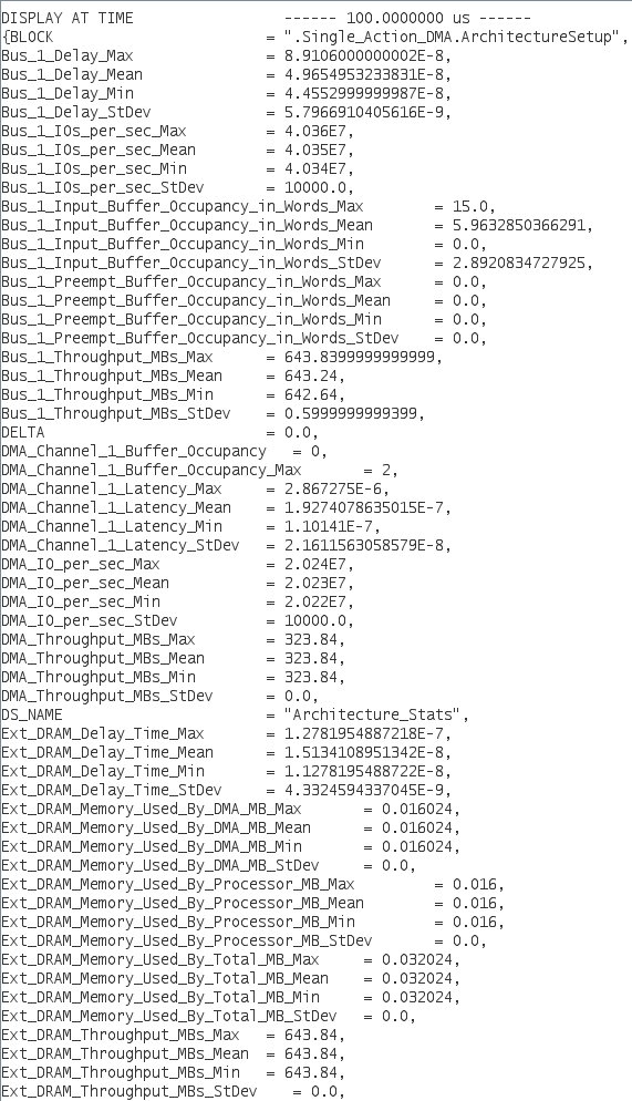
With that we get the following baseline Latency and throughput numbers:
Experiment 1:
So we will startup with
altering the Outstanding_Req_Count to 2. This will mean that the DMA
will dispatch two requests before pausing and waiting for the resonse
of the sent requests.
We will be using the following parameters:
Outstanding_Req_Count: {1,1}
Data Size: 32
Burst Size: 32
Width_Bytes: 4
Number of Channels 1
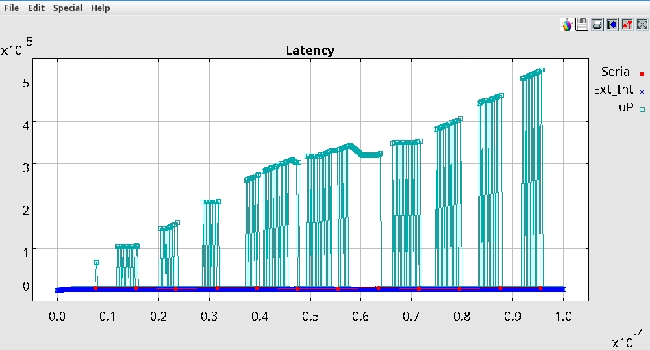
With that we get the following results
Note: We see that the transactions
are a lot more grouped in the case of uP traffic.We can also see a
slight uptake in the throughput. Another point to not is the overall slight increase in latency for uP.
Experiment 2:
Starting off with the
baseline, we will now change the Burst Size, taking it down to 16
bytes. Since our Data Size is remaining the same at 32 bytes, setting
the burst size to half that means that the transaction will get
fragmented into two parts.
We will be using the following parameters:
Outstanding_Req_Count: {1,1}
Data Size: 32
Burst Size: 16
Width_Bytes: 4
Number of Channels 1
With that we get the following results
Note: Since the transactions
are smaller they take less time to complete, and so we see only a single jump in
Latency that we saw in the baseline. Our latency has gone up by a
little bit however the more pressing matter is our throughput which has
now dropped by about 25%. And since our transactions have not slowed
down, this bottleneck is also reflected in the buffer occupancy which
has increased compared to the baseline. Should this simulation go on
long enought there is a possibility of the buffer getting completely
filled up.
Experiment 3:
Now let us look at a bit
of an odd configuration, to present an error condition, where Starting
off with the
baseline, we will now change the Word Size, taking it down to 16
bytes. We will also disconnect the relations Traffic2 and Traffic3 to
the rest of the model, leaving only Traffic (Serial write). We will
also limit the number of transactions produced by Traffic block to 8
(because each of these transactions are 4 bytes and 8 of these will
make 32 bytes, the capacity of our Serial FIFO buffer), triggering a
single transaction toward the DMA. This can be done inside by setting
the setting the parameter Number_of_transactions to 8. We will also be
applying listen-to-port on Req input port of the DMA and simultaneously
listen to the output port Ack of the DMA.
We will be using the following parameters:
Outstanding_Req_Count: {1,1}
Data Size: 16
Burst Size: 32
Width_Bytes: 4
Number of Channels 1
In the Listen to port windows you will see that a single
transaction in both of them. As might have assumed, we should have seen
2 transactions coming out of the DMA since our input was 32 bytes and,
having set DMA Data Size to 16, the output port Ack is emitting 16
bytes. We can also look at the field variables, the A_bytes field for
the input port Req says 32 but A_bytes at the output port Req says 16
(the same as DMA Data size). This clearly shows data lose. The extra 16
bytes were discarded by the DMA.
Experiment 4:
Now let us change the
Width_Bytes. This is the width with which the DMA is connected to the
interface block. We will set it to 8 bytes or 64-bit.
We will be using the following parameters:
Outstanding_Req_Count: {1,1}
Data Size: 32
Burst Size: 32
Width_Bytes: 8
Number of Channels 1
We get the following results:
We can see that the overall latency is lower, we can also see that the
DMA_throughput is also higher. Although it is important to note that
the width of the bus is usually an expensive paramerter to alter so is
usually not prefered.
Experiment 5:
We will now change the
number of channels. Since we currently have two devices using the DMA,
we can assign each of them a single channel. We do that by changing the
number of chnnels in the DMA controller to 2 and then in
ExpressionList2, change input.A_DMA_Channel = {1} to
input.A_DMA_Channel = {2}.
We will be using the following parameters:
Outstanding_Req_Count: {1,1}
Data Size: 32
Burst Size: 32
Width_Bytes: 4
Number of Channels 2
Here we get the following results
Now as you can see we have not seen any meaningful positive change. You
might thing that there is no reason to do this if we don't see any
imporovement, however the important aspect of this is that since we
have two separate channels we can configure them separately. This is
illustrated in the next experiment.
Experiment 5:
We Continuing from the
previous experiment, keeping the channel number at 2. We will now also
change the Outstanding_Req_Count for channel 1 only.
We will be using the following parameters:
Outstanding_Req_Count: {2,1}
Data Size: 32
Burst Size: 32
Width_Bytes: 4
Number of Channels 2
Here we get the following results
We can see a significant drop in the latency and this is with almost
the same throughput as Experiment 4. Here we can also see an importance
of multiple variable at the same time.
Buffer occupancy Issue
Now that we have made ourselves familiar with some of the parameters
that can affect our results in a bottlenecked situation. we will now
address the biggest issure, the increasing latency graph. This clearly
means as time goes on the latency will keep on increasing, as we are
being limited by our Bus Speed. Since the traffic being generated does
not change, we wil eventually fill up our buffer, which can be
confirmed by running the simulation for much longer. We wil now try to
increase our Bus Speed. You can experiment with a few configurations, a
working configuration is 202 Mhz, set this in the Bus_Speed_Mhz global
paramerter. Also we will be keeping the configuration from Experiment
5.
With that we get the following results:
As you can see the latency is stable and no longer increasing. This
might make you think that all that experminatation we did was entirely
useless. However that is not actually the case. We can demonstract that
be using our baseline and only increasing the Bus Speed.
With that we get the following results
As you can see the latency is still rising. We can now implement the Outstanding_Req_Count, setting it to {2}.
With that we get the following results.
Is you can clearly see, without the Outstanding_Req_Count parameter
change we would have had to push Bus Speed much higher. With some
experimentation, we were able to mitigate that.
Read & Write Sequence
The model at this point has been setup to only conduct a read operation
on the Ext_DRAM. We can change that by changing the action sequence
used in ExpressionList8. Try changing the DMA related fields as shown
below, such that the DMA Controller does a Read followed by a Write.

Now run the model again and observe the difference in the the output latency.
Notes
- Compare the utilization of the different devices in the Text window.
- Also, notice the delays for
the high priority and low priority transaction. Vary the priorities and
measure the resulting performance.
- Observe the bus buffer occupancy to see if the data is overflowing.
- How is the priority handled between the processor, Serial Port and Ext_to_Int?
Hint: The bus reorders the
transactions based on priority.