FlexRay Bus
Architecture Model
Click
here to view and Simulate the FlexRay VisualSim model
1 FlexRay Overview
FlexRay is a new
network communication system targeted specifically at the next generation of
automotive applications or "by-wire" applications. The by-wire applications
demand high-speed bus systems that are deterministic, fault-tolerant, and
capable of supporting distributed control systems. The technology
is designed to meet key automotive requirements like dependability,
availability, flexibility, and a high data rate to complement the major
in-vehicle networking standards - CAN, LIN, and MOST.
FlexRay, as a scalable communication system, allows synchronous and
asynchronous data transmission. The synchronous data transmission enables time
triggered communication to meet the requirement of dependable systems. The
asynchronous transmission, based on the fundamentals of the byteflight™
protocol, allows each node to use the full bandwidth for event driven
communications. FlexRay's synchronous data transmission is deterministic with a
minimum message latency and message jitter guaranteed. FlexRay supports
redundancy and fault-tolerant distributed clock synchronization for a global
time base, thus keeping the schedule of all network nodes within a tight,
predefined precision window.
2 Introduction
Mirabilis Design provides a modeling and simulation environments around
the FlexRay and CAN bus network architectures. The tutorial and white paper below helps understand
the operation of FlexRay in general and to use the VisualSim model to analyze
different conditions. The model link
provided above helps the user to fall through using the model Applet. This link opens a separate Web Page where the
interactive FlexRay model will appear. The user can click on the icons of the
communication channel, nodes, star and the top-level parameters, modify them
and execute the simulation. This will
enable the user to study impact on their architectures and to optimize the
FlexRay parameters. A list of analysis
is provided below.
The Automotive Library contains the following components of FlexRay-
- Communication
Controller
- Node
- Star
- Dual Channel
- Variety of
Network topology examples including mesh,
- Example
systems including rollover prevention in an Anti-lock Braking System (ABS).
- Traffic
generators to activate the model and construct scenarios
The Automotive Library in VisualSim can be used to construct automotive network
topologies and interconnect sub-system across this backbone. Architects can
utilize the FlexRay Bus architecture model in VisualSim for validating the
operation of a sub-system, evaluate performance for different FlexRay bus
topologies, sizing an Electronic Control Units, or optimizing the FlexRay
protocols for future revisions.
Architects can also use the FlexRay Bus model to optimize the FlexRay bus
static and dynamic slot assignments in terms of number of slots and the size of
slots that may be available from different vendors. The FlexRay
Bus Model is based on the FlexRay – Protocol – Specification – V2.1,
The following analysis can be constructed using these models:
- Task
Latency requiring data from multiple sensors and processed at an ECU
- Performance
impact for different network topology or parameter configurations
- Determine
the number of devices connected
- Performance
vs. reliability trade-off by using the Dual Channel for additional bandwidth
or redundant links.
- Create
multi-system configuration to evaluate real-time performance impact of
shared network topology and traffic loading.
- Size
the over 35 variables of the FlexRay protocol such as number of slots slot
size and node buffer
- Design
protocol conversion algorithms and bus gateway between different speed
FlexRay, CAN and in-system networks.
- Evaluate
proprietary or alternate extension to the FlexRay standard such as BMW Byteflight™
- Evaluate
system reliability by injecting an error into the channel or create
downtime at a port
A Two Port FlexRay Bus Model in VisualSim is shown in Figure 1 and is described
in detail in this document. Bus Statistics are generated for each bus channel,
and each assigned bus slot in the protocol.
The collected statistics include:
- Channel 1 and
Channel 2 frame utilization percent
- Channel 1 and
Channel 2 aggregate throughput (Kbps), and latency (sec)
- Per Channel,
per Slot aggregate throughput (Kbps), and latency (sec)
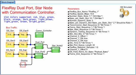
Figure 1‑0
3
FlexRay Bus Model Capabilities
The FlexRay Bus Model is based on
the FlexRay – Protocol – Specification – V2.1, 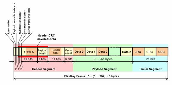
Figure 2‑0 FlexRay Frame Format
VisualSim provides the
FlexRay_Frame_DS to set the above data as integers, if desired.
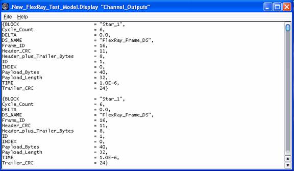
Figure 3‑0 VisualSim FlexRay_Frame_DS
A user can set the
FlexRay_Frame_DS fields for Frame_ID, Payload_Length, Payload_Bytes,
Header_CRC, Cycle_Count, Payload_Bytes, or Trailer_CRC external to the bus
model. The most important user field is
the Payload_Bytes field, this tells the FlexRay Bus port how many
format frames may be needed. The FlexRay Bus model operation is based on
the detailed frame encoding for the static and dynamic segments. Figure 4, below shows the frame encoding for
the static segment of the FlexRay bus.
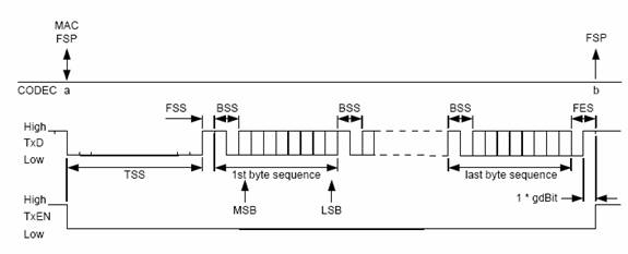
Figure 4‑0 FlexRay Static Segment Frame Encoding
The FlexRay Bus Model provides
similar encoding with the parameters shown below.
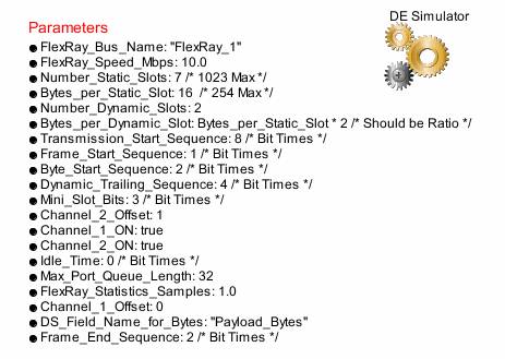
Figure 5‑0 VisualSim Static/Dynamic Segment Frame Parameters
The VisualSim modeling parameters
provide for the Number_of_Static_Slots parameter, 1023 maximum, according to the FlexRay
specification. The model can actually
run with more slots than 1023, however, practical considerations of Kbps per
slot may preclude more and more slots as a viable design solution. More slots executing in a system may increase
power consumption and add some bookkeeping complexity. Each
Equation
1. Bit Time (sec) = 1.0 / (FlexRay_Speed_Mbps * 1.0E06)
In addition, the following
parameters can be set according to the FlexRay specification in terms of bit
times:
- Transmission_Start_Sequence
- Frame_Start_Sequence
- Byte_Start_Sequence
- Frame_Ending_Sequence
- Dynamic_Trailing_Sequence
Next the encoding for the dynamic
segment is shown.
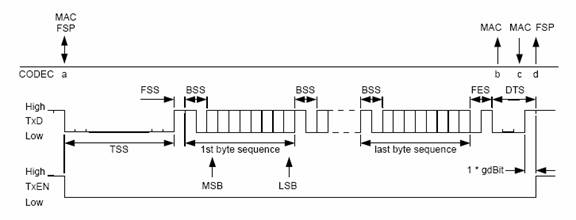
Figure 6‑0 FlexRay Dynamic Segment Frame Encoding
The VisualSim FlexRay Bus Model
provides the Dynamic_Trailing_Sequence (bit times) parameter to the existing encoding. Another parameter, Idle_Time (bit times)
between Dynamic and Static segments, can be used to control the overall bus
timing.
Slot assignments are made at the
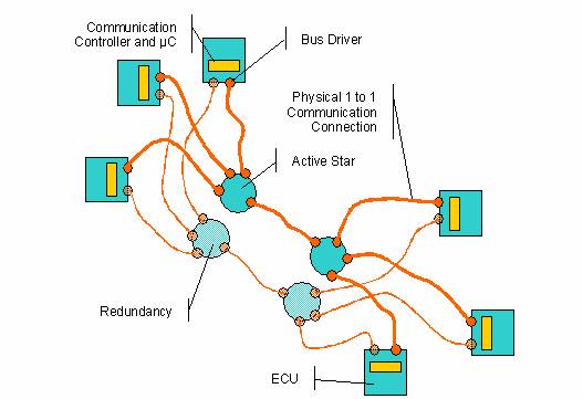
Figure 7‑0
Typical FlexRay Bus Topology with Active Star Nodes
The VisualSim FlexRay bus model is identical to the above
topology, with dual port bus nodes, and four port active star nodes. In addition, the VisualSim FlexRay bus model
has a common Communication Controller to define the Static and Dynamic slot
configuration for all Dual Ports in the model, monitors channel/slot activity,
and provides bus statistics of same. Think
of the VisualSim Communication Controller as containing the Communication Cycle
setup in one convenient place in the model, as to reduce the information
entered into each
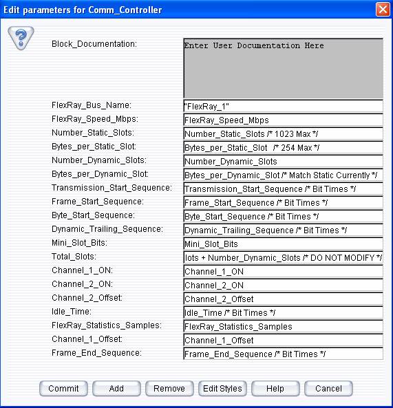
Figure 8‑0
FlexRay Communication Controller Parameters
One can turn off the plot for Channel 1 or 2 with the Channel_1_ON and Channel_2_ON parameters. In addition, one can set the offset line they plot using the Channel_1_Offset or Channel_2_Offset parameters. The Static and Dynamic slot offsets are calculated according to the following equations:
Equations
2, 3.
Static Offset = (Transmission_Start_Sequence +
Frame_Start_Sequence +
Byte_Start_Sequence) * Bit Time
Dynamic Offset = (Frame_End_Sequence
+ Transmission_Start_Sequence +
Frame_Start_Sequence
+ Byte_Start_Sequence) * Bit Time
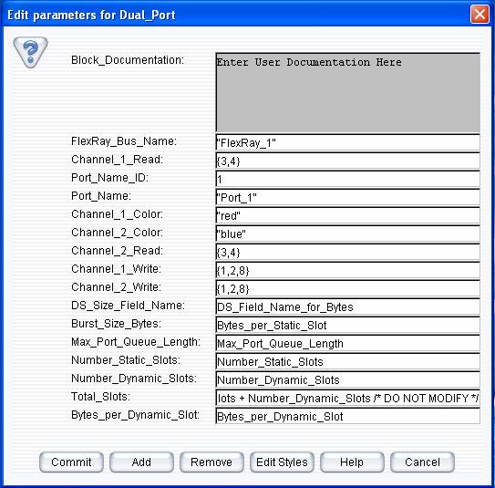
Figure 9‑0
One will note that the user can set the color of the
ports in Channel_1_Color and Channel_2_Color parameters. These colors will be applied to the slots
identified for the parameters Channel_1_Write
and Channel_2_Write of this
Channel_1_Read, Channel_2_Read is an array of slot number consistent with the
Communication Controller. If there are 7
static slots and 2 dynamic slots, the 1 -7 identify static assignments, then 8,
9 assign dynamic assignments. If a
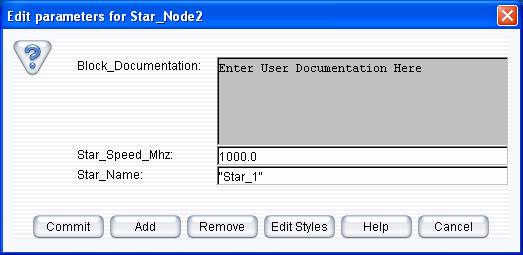
Figure 10‑0 FlexRay Star Node Parameters
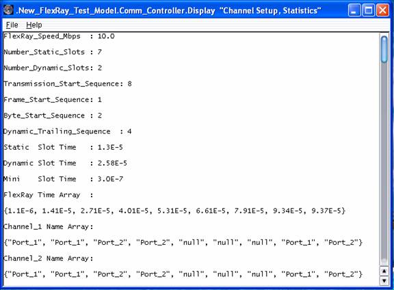
Figure 11‑0 FlexRay Channel, Slot Setup Summary
Figure 12‑0
FlexRay Bus Modules
Figure 12‑0 FlexRay Modeling Modules
MAC Layer Processing
The MAC layer processing is predicated on assigning the
Static and Dynamic slots, based on the user parameter settings. If a
The model Dual Port and Star Nodes operate identically to chip level components in terms of throughput/latency performance and port buffering (Max_Port_Queue_Length parameter), based on the static and dynamic slot assignments. FlexRay slot assignments include the size (Bytes_per_Static_Slot, Bytes_per_Dynamic_Slot parameters) and the number of slots in the Communication Cycle(Number_Static_Slots, Number_Dynamic_Slots parameters). Currently, the VisualSim FlexRay model expects the Bytes_per_Dynamic_Slot to simply be a multiple, or ratio, of the Bytes_per_Static_Slot. For example, the Bytes_per_Dynamic_Slot could be 1X, 2X, 3X, or 4X of the Bytes_per_Static_Slot parameter. This minor constraint was added to improve overall model performance, so accesses to the input buffer can be in equal amounts from the buffer.
The MAC layer portion of the
The MAC layer also processes intermediate FlexRay frames once a transmission completes, or if a Dynamic Mini-Slot encountered an ongoing transmission, the MAC layer will reschedule the frame transmission when the current Dynamic Slot completes.
4 FlexRay Bus Model Analysis
The FlexRay Bus Model provides the ability to analyze
individual channel and slot performance in terms of throughput, latency, more
importantly, the ability to see the data being written by
to
Channel_1 Name Array (Static Slots 1 through 7 [red], Dynamic Slots 8, 9 [blue]):
{"Port_1", "Port_1", "Port_2", "Port_2", "null", "null", "null", "Port_1", "Port_2"}
Channel_2 Name Array (Static Slots 1 through 7 [red], Dynamic Slots 8, 9 [blue]):
{"Port_1", "Port_1", "Port_2", "Port_2", "null", "null", "null", "Port_1", "Port_2"}
Dual Port 2, Channel 2 Write Color: “orange”
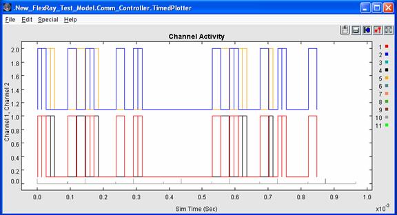
Figure 13‑0 FlexRay Channel, Slot Activity Plot
This plot shows Dual Port 1 in red and blue in the plot, sending twice as much data as Dual Port 2 in black and orange, which is consistent with the top level system diagram. The top level system modeling diagram has two traffic sources for Dual Port 1, while Dual Port 2 has only one traffic source. The grey markers at the bottom of the plot indicate the static and dynamic portion of the Communication Cycle.
Two Port FlexRay Bus Model -- Statistics generated by the Model
Channel Statistics
A_Channel_1_Utilization =
38.4000000384,
A_Channel_2_Utilization = 38.4000000384,
B_Channel_1_Max_Kbps =
879.1208791208792,
B_Channel_1_Mean_Kbps =
549.4505494505496,
B_Channel_1_Min_Kbps =
219.7802197802198,
B_Channel_1_StDev_Kbps =
219.7802197802194,
C_Channel_1_Max_Delay =
3.84E-4,
C_Channel_1_Mean_Delay =
2.368E-4,
C_Channel_1_Min_Delay =
1.024E-4,
C_Channel_1_StDev_Delay = 9.656721320752E-5,
D_Channel_2_Max_Kbps =
879.1208791208792,
D_Channel_2_Mean_Kbps =
549.4505494505496,
D_Channel_2_Min_Kbps =
219.7802197802198,
D_Channel_2_StDev_Kbps =
219.7802197802194,
E_Channel_2_Max_Delay =
3.84E-4,
E_Channel_2_Mean_Delay =
2.368E-4,
E_Channel_2_Min_Delay =
1.024E-4,
E_Channel_2_StDev_Delay = 9.656721320752E-5,
Channel 1 Slot Statistics
F_Channel_1_Slot_0_Max_Delay = 3.0410000008E-4,
F_Channel_1_Slot_0_Max_Kbps = 109.8901098901099,
F_Channel_1_Slot_0_Mean_Delay = 1.6234000008E-4,
F_Channel_1_Slot_0_Mean_Kbps = 91.5750915750916,
F_Channel_1_Slot_0_Min_Delay = 1.290000008E-5,
F_Channel_1_Slot_0_Min_Kbps = 0.0,
F_Channel_1_Slot_0_StDev_Delay = 1.0306210942922E-4,
F_Channel_1_Slot_0_StDev_Kbps = 40.9536259615346,
F_Channel_1_Slot_1_Max_Delay = 3.1710000004E-4,
F_Channel_1_Slot_1_Max_Kbps = 109.8901098901099,
F_Channel_1_Slot_1_Mean_Delay = 1.7534000004E-4,
F_Channel_1_Slot_1_Mean_Kbps = 91.5750915750916,
F_Channel_1_Slot_1_Min_Delay = 2.590000004E-5,
F_Channel_1_Slot_1_Min_Kbps = 0.0,
F_Channel_1_Slot_1_StDev_Delay = 1.0306210942922E-4,
F_Channel_1_Slot_1_StDev_Kbps = 40.9536259615346,
F_Channel_1_Slot_2_Max_Delay = 1.8450000004E-4,
F_Channel_1_Slot_2_Max_Kbps = 109.8901098901099,
F_Channel_1_Slot_2_Mean_Delay = 1.1490000005333E-4,
F_Channel_1_Slot_2_Mean_Kbps = 54.945054945055,
F_Channel_1_Slot_2_Min_Delay = 3.890000008E-5,
F_Channel_1_Slot_2_Min_Kbps = 0.0,
F_Channel_1_Slot_2_StDev_Delay = 5.9612973962385E-5,
F_Channel_1_Slot_2_StDev_Kbps = 54.945054945055,
F_Channel_1_Slot_3_Max_Delay = 1.3430000008E-4,
F_Channel_1_Slot_3_Max_Kbps = 109.8901098901099,
F_Channel_1_Slot_3_Mean_Delay = 9.310000006E-5,
F_Channel_1_Slot_3_Mean_Kbps = 36.6300366300366,
F_Channel_1_Slot_3_Min_Delay = 5.190000004E-5,
F_Channel_1_Slot_3_Min_Kbps = 0.0,
F_Channel_1_Slot_3_StDev_Delay = 4.120000002E-5,
F_Channel_1_Slot_3_StDev_Kbps = 51.8026945924211,
F_Channel_1_Slot_7_Max_Delay = 3.4600000008E-4,
F_Channel_1_Slot_7_Max_Kbps = 219.7802197802198,
F_Channel_1_Slot_7_Mean_Delay = 1.9656000008E-4,
F_Channel_1_Slot_7_Mean_Kbps = 183.1501831501832,
F_Channel_1_Slot_7_Min_Delay = 5.480000008E-5,
F_Channel_1_Slot_7_Min_Kbps = 0.0,
F_Channel_1_Slot_7_StDev_Delay = 1.0306210942922E-4,
F_Channel_1_Slot_7_StDev_Kbps = 81.9072519230692,
F_Channel_1_Slot_8_Max_Delay = 2.1370000008E-4,
F_Channel_1_Slot_8_Max_Kbps = 219.7802197802198,
F_Channel_1_Slot_8_Mean_Delay = 1.4623333338667E-4,
F_Channel_1_Slot_8_Mean_Kbps = 91.5750915750916,
F_Channel_1_Slot_8_Min_Delay = 8.090000004E-5,
F_Channel_1_Slot_8_Min_Kbps = 0.0,
F_Channel_1_Slot_8_StDev_Delay = 5.4236355187469E-5,
F_Channel_1_Slot_8_StDev_Kbps = 98.6293920720605,
Channel 2 Slot Statistics
G_Channel_2_Slot_0_Max_Delay = 3.0410000004E-4,
G_Channel_2_Slot_0_Max_Kbps = 109.8901098901099,
G_Channel_2_Slot_0_Mean_Delay = 1.6234000004E-4,
G_Channel_2_Slot_0_Mean_Kbps = 91.5750915750916,
G_Channel_2_Slot_0_Min_Delay = 1.290000004E-5,
G_Channel_2_Slot_0_Min_Kbps = 0.0,
G_Channel_2_Slot_0_StDev_Delay = 1.0306210942922E-4,
G_Channel_2_Slot_0_StDev_Kbps = 40.9536259615346,
G_Channel_2_Slot_1_Max_Delay = 3.1710000008E-4,
G_Channel_2_Slot_1_Max_Kbps = 109.8901098901099,
G_Channel_2_Slot_1_Mean_Delay = 1.7534000008E-4,
G_Channel_2_Slot_1_Mean_Kbps = 91.5750915750916,
G_Channel_2_Slot_1_Min_Delay = 2.590000008E-5,
G_Channel_2_Slot_1_Min_Kbps = 0.0,
G_Channel_2_Slot_1_StDev_Delay = 1.0306210942922E-4,
G_Channel_2_Slot_1_StDev_Kbps = 40.9536259615346,
G_Channel_2_Slot_2_Max_Delay = 1.8450000008E-4,
G_Channel_2_Slot_2_Max_Kbps = 109.8901098901099,
G_Channel_2_Slot_2_Mean_Delay = 1.1490000006667E-4,
G_Channel_2_Slot_2_Mean_Kbps = 54.945054945055,
G_Channel_2_Slot_2_Min_Delay = 3.890000004E-5,
G_Channel_2_Slot_2_Min_Kbps = 0.0,
G_Channel_2_Slot_2_StDev_Delay = 5.9612973996382E-5,
G_Channel_2_Slot_2_StDev_Kbps = 54.945054945055,
G_Channel_2_Slot_3_Max_Delay = 1.3430000004E-4,
G_Channel_2_Slot_3_Max_Kbps = 109.8901098901099,
G_Channel_2_Slot_3_Mean_Delay = 9.310000006E-5,
G_Channel_2_Slot_3_Mean_Kbps = 36.6300366300366,
G_Channel_2_Slot_3_Min_Delay = 5.190000008E-5,
G_Channel_2_Slot_3_Min_Kbps = 0.0,
G_Channel_2_Slot_3_StDev_Delay = 4.119999998E-5,
G_Channel_2_Slot_3_StDev_Kbps = 51.8026945924211,
G_Channel_2_Slot_7_Max_Delay = 3.4600000004E-4,
G_Channel_2_Slot_7_Max_Kbps = 219.7802197802198,
G_Channel_2_Slot_7_Mean_Delay = 1.9656000004E-4,
G_Channel_2_Slot_7_Mean_Kbps = 183.1501831501832,
G_Channel_2_Slot_7_Min_Delay = 5.480000004E-5,
G_Channel_2_Slot_7_Min_Kbps = 0.0,
G_Channel_2_Slot_7_StDev_Delay = 1.0306210942922E-4,
G_Channel_2_Slot_7_StDev_Kbps = 81.9072519230692,
G_Channel_2_Slot_8_Max_Delay = 2.1370000004E-4,
G_Channel_2_Slot_8_Max_Kbps = 219.7802197802198,
G_Channel_2_Slot_8_Mean_Delay = 1.462333334E-4,
G_Channel_2_Slot_8_Mean_Kbps = 91.5750915750916,
G_Channel_2_Slot_8_Min_Delay = 8.090000008E-5,
G_Channel_2_Slot_8_Min_Kbps = 0.0,
G_Channel_2_Slot_8_StDev_Delay = 5.4236355154298E-5,
G_Channel_2_Slot_8_StDev_Kbps = 98.6293920720605,
The slot statistics are 0-based numbers, meaning 0 corresponds to slot 1, etc. These statistics provide the user with detailed information about the throughput and latency of each slot on each channel of the FlexRay bus. In addition, the channel level statistics provides utilization values in percent for each channel, in terms of time transmitting frames. The maximum utilization of each channel will be less than 100%, based on the settings of the inter-frame spacing.
Dynamic Slot Analysis
One will notice that the two dynamic slots in this model have similar maximum Kbps values, meaning they were filled without contention. Again, the two Dynamic Slots are 7, 8 in the statistics listing, above. The mean Kbps values for the two slots are in proportion to the traffic being double on Dual Port 1, versus Dual Port 2. Similarly, the maximum delay on Dual Port 1 is greater than Dual Port 2 as the MAC layer buffers transactions for Dual Port 1 from two sources, resulting in the greater slot latency statistics.
Presently, the Two Port FlexRay Bus Model allows the user to assign a fixed number of dynamic slots, based on the Number_Dynamic_Slots parameter, and allows the user to define dynamic slot widths in proportion to the number of Bytes_per_Static_Slot. One variation of this dynamic slot assignment might be to allow for over-subscription of dynamic slots, by limiting the “available” dynamic slots in the Communication Cycle. This can be accomplished by a modification to the MAC layer processing of each dynamic frame.
Number and Size of Static/Dynamic Slots
The VisualSim FlexRay bus model can be used to determine the optimum number of slots and their size, by running different slot configurations, realizing that smaller slots reduce overall frame latency for incoming transactions, while larger slots improve bandwidth utilization with fewer overhead bytes as a percentage of each frame. In addition, smaller static or dynamic slots may increase power consumption, as a result of more headers being transmitted as well. The model can help establish the best combination of both throughput, and latency for time-critical information, extra-bandwidth critical information, or both.