Multi_AXI_to_Memory_Access
Below graphic (In italics): Hover over icons to view parameter and values. Click on icons to view the internals (if provided)
Size the memory and the Bus topology to meet the read and write latency
Blocks used: Traffic block for Master requests, AXI, Memory Controller and Cycle-Accurate DRAM
Experiments: Change (1) sequential to random address, (2) Ratio of read/write
Launch Demo
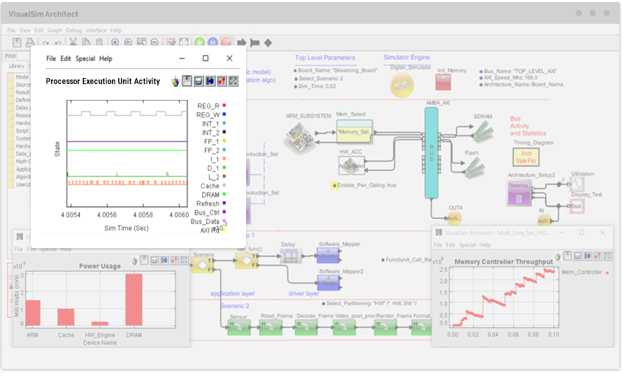
Power_Perf_example
Below graphic (In italics): Hover over icons to view parameter and values. Click on icons to view the internals (if provided)
Assign tasks to processor and hardware accelerators to meet the power requirements (<1W) and performance(>13,000 frames per second) for this ARM-based SoC
Blocks used: ARM9, AXI, DRAM, Flash, TLB, Use case mapper, Power Table
Experiments: Image Rotate is (1)SW, (2) HW, (3) HW with Power Management
Launch Demo
software_tasks_w_Power
Below graphic (In italics): Hover over icons to view parameter and values. Click on icons to view the internals (if provided)
Select the architecture with the lowest latency and the most efficient- highest processing/communication ratio
Blocks used: SystemResource, Use case mapper, Power Table
Experiments:Vary (1) Bus Speeds, (2)Processor Speed
Launch Demo
Flow_Control_Xon_Xoff
Below graphic (In italics): Hover over icons to view parameter and values. Click on icons to view the internals (if provided)
Evaluate the Quality of Service for the Round-Robin arbitration with Egress credit for each channel. Goal is to keep
the latency in a small range and not view an increasing value that indicates queuing
Blocks used: Queue, Server, Traffic and Script(for Arbitration)
Experiments:Vary (1) Scan speed for arbiter, (2)Number of channel, (3) Egress threshold
Launch Demo
CAN_Bus_w_Bridge6
Below graphic (In italics): Hover over icons to view parameter and values. Click on icons to view the internals (if provided)
A multi-protocol automotive network with all the ECUs, sensors (CANdb format) and messages (CANdb format) to
form the full vehicle model. Measure the latency from Node to Node for sensor
to ECU and Diagnostic node to all the ECUs. Generate the power consumed by the CAN network.
Blocks used: CAN, CAN-FD, Ethernet, Bridge, Sensor and Message database, Power Table
Experiments:Vary (1) CAN to CAN_FD, (2) Ethernet topology from Star to Linear
Launch Demo
VoIP_Load_SR
Below graphic (In italics): Hover over icons to view parameter and values. Click on icons to view the internals (if provided)
Generate a burst of traffic to create a large delay for voice packets, increase latency and reduce the Quality of Service. Measure the resource usage in each of the hardware modules
Blocks used:Queues, Servers, Ethernet Node, SystemResource and Traffic
Experiments: Vary (1) Enable_Load to true, (2) Packet Rate
Launch Demo
 SEAL- Interactive Training Modules▼