
Browsable image of the model.
A Network on Chip (NoC) is typically a communication subsystem on an IC. They are commonly used in conjunction with the cores within SoCs to bring out notable improvements to the entire system over conventional bus interconnections.
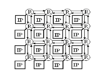
Diagram No.1 NoC Architecture
Routers are used between the Nodes(Cores) to transfer data and requests. The current design is based on the ARM Corelink Cache Coherent Network which is used as a cache coherency mechanism in a system with several IP Cores. The types of devices present in the NoC are Request Nodes, Home Nodes, and Routers. There are two types of request and home nodes which are modelled in this project. RNF (Fully Coherent Request Node), RNI (I/O Request Node), HNF (Fully Coherent Home Node), and HNI (I/O Home Node). The RNFs are fully coherent master devices that represent the processor cores in the NoC. The HNFs act as coherent region of the Memory which take in requests from the RNFs, handle snoops, and communicate with the cache and DRAM, and handles responses and acknowledgements. The RNIs and HNIs represent the I/O devices where the RNI sends data to the HNI, which acts as a sink.
The RNFs are typically traffic sources that produce and pass on requests to the Home Nodes. Expression List blocks and Script blocks are used to add fields to the data structure. Some of these fields are Request Type, Request Size, Data Size, Memory Address, Priority, Source and Destination addresses. Currently four Request Types are being used which are, ReadNoSnp, ReadSnp, WriteNoSnp, and WriteSnp. Each request types are handled differently by the Home Node. The input port of the RNF receives responses, acknowledgements, and data from the home nodes.
HNFs act as smart memory interface blocks within the NoC. They receive and processes the requests received from the Request nodes. The HNF stores all the incoming requests in 16 queues depending on their priorities. It then uses a popping mechanism based on an algorithm that uses wait times, priority levels, and round robin arbitration within priority groups to pop the right queue at the right time. The HNF also updates the database when a new request comes in to facilitate snoops. When the requests come out of the queue, a script is used to make the Home Node react differently to each type of requests.
HNF sends a response back to the Request Node. Sends a read request for the corresponding address to the Cache. The Cache sends data back to the HNF which in turn is sent to the Request Node.
HNF sends a response back to the Request Node. It checks the database to see if any other Request Node has written the data at the same address before. If already written, it sends a data snoop request to the other RNF. The other RNF, after receiving the snoop request sends the data back to the HNF. Now the HNF forwards the data to the original RNF which requested the data. If the HNF did not find a previous write on the same address by other RNFs, it sends a read request to the Cache and sends the data back to the RNF.
HNF sends a response back to the Request Node. The RNF, after receiving the response from the HNF, sends the data to be written. The HNF gets the data and passes it on to the Cache. After writing the Cache sends a response to the HNF, which in turn will send an Acknowledgment back to the RNF.
HNF sends a response back to the Request Node. The HNF checks the database to see if any previous reads have occurred on the same address by other request nodes. If Yes, the HNF sends notifications to the corresponding RNFs. The RNF, after receiving the response for data from the HNF, sends the data to be written. The HNF gets the data and passes it on to the Cache. After writing the Cache sends a response to the HNF, which in turn will send an Acknowledgment back to the RNF.
RNF_1 sends Request to HNF_1 –> HNF_1 sends Response to RNF_1 –> HNF_1 reads Local Cache –> HNF sends Data to RNF_1
RNF_1 sends Request to HNF_1 –> HNF_1 sends Response to RNF_1 –> HNF_1 reads Database –> If Data already written by RNF_2 ? ? –> Yes = HNF sends Data Request to RNF_2
–> RNF_2 sends Data to HNF_1
–> HNF_1 sends Data to RNF_1
? –> No = HNF reads Cache –> HNF sends Data to RNF
RNF_1 sends Request to HNF_1 –> HNF_1 sends Response to RNF_1 -> RNF_1 sends Data to HNF –> HNF_1 writes Data to Cache–> HNF_1 sends Ack to RNF_1 after writing
RNF_1 sends Request to HNF_1 –> HNF_1 sends Response to RNF_1 –> HNF_1 reads Database –> If Data already read by RNF_2 ?
? –> Yes = HNF_1 Informs RNF_2
–>RNF_1 sends Data –> HNF_1 writes Data to Cache
–> HNF_1 sends Acknowledgement to RNF_1 after writing
I/O request nodes are simple traffic generators that produce data packets to send them to a I/O Home Node.
I/O home nodes are sinks where the data received from the RNIs and RNFs are sent through the I/O device.
Router blocks within the SoC guide the incoming requests and data to the right path by reading the destination field of the packets. The current design of the routers support two types of routing methods.
(i) Incoming packets possess the path from source to destination
(ii) Incoming packets possess the destination address alone
The router contains a crossbar which acts as the primary delay for the coming through. The crossbar has 4 Server blocks in total where each of them pass a different request type and data with a user defined delay.
The router also supports 2 devices at a time, where the device can be a home node or a request node. The routers also use the databases “Routing Table” and “Forwarding Table” to find the destination of the packets. A delay block is added to the wires between two routers to account for the overall wire delay.
Router_C_AddressA_Destination Router_Hop_Address;
“R_1_1” “RNF_1” “0x00001”; /*Device*/
“R_1_1” “RNI_1” “0x00006”; /*Device2*/
“R_1_1” “R_1_2” “0x00003”; /*East*/
“R_1_1” “R_2_1” “0x00004”; /*South*/
“R_1_1” “HNF_1” “0x00004”; /*South*/
“R_1_1” “HNI_1” “0x00004”; /*South*/
“R_1_2” “RNF_3” “0x00001”; /*Device*/
“R_1_2” “RNF_1” “0x00005”; /*West*/
“R_1_2” “RNF_4” “0x00006”; /*Device2*/
“R_1_2” “R_1_1” “0x00005”; /*West*/
“R_1_2” “R_2_2” “0x00004”; /*South*/
“R_1_2” “HNI_1” “0x00003”; /*East*/
“R_1_2” “HNF_1” “0x00004”; /*South*/
“R_2_1” “HNI_1” “0x00001”; /*Device*/
“R_2_1” “RNF_6” “0x00006”; /*Device2*/
“R_2_1” “R_1_1” “0x00002”; /*North*/
“R_2_1” “R_2_2” “0x00003”; /*East*/
“R_2_1” “HNF_1” “0x00003”; /*East*/
“R_2_1” “HNI_1” “0x00001”; /*Device*/
“R_2_1” “RNF_1” “0x00002”; /*North*/
“R_2_2” “HNF_1” “0x00001”; /*Device*/
“R_2_2” “R_1_2” “0x00002”; /*North*/
“R_2_2” “R_2_1” “0x00005”; /*West*/
“R_2_2” “RNF_1” “0x00005”; /*West*/
“R_2_2” “RNF_3” “0x00002”; /*North*/
VisualSim AMBA Corelink CMN600 library enables architects to explore the topology of the SoC using the CMN600 as the NoC. The library block supports devices, connectivity between routers, flits, fragmentation-assembly, virtual LAN, routing, snoop and separate channels for request, response, data and acknowledge.
The library consists of the following blocks:
Apart from this there are configuration blocks
To view the documentation for each block, right-click on the block and select Get Documentation.
To assemble the model


