Introduction
Autonomous Driver Assistance Systems (ADAS) are now an upsurging technology in the automotive space. As these technologies become more pervasive, it becomes increasingly important for consumers to be informed about the systems on their vehicle and their functionality. However, several names marketed by producers, manufacturers, and the lack of consensus by industry regulatory groups, make it difficult for consumers to discern what features a vehicle has and how they actually work.
In recent years, the developments in traffic and technology caused an increasing interest in the analysis of interactions between road users. On highways, traffic intensity and traffic density increase rapidly. Therefore, drivers have to respond to each other to a higher extent and to adapt their driving etiquette rapidly to navigate other drivers. Several studies have dealt with this topic. Hence, there is a demand for understanding the behavior of driving and analyzing interactions between road users.
Various research methodologies were developed to respond to this demand:
- Experimental runs with many real drivers in natural situations on real roads
- Simulation of driving, by exposing a single human driver to simulated traffic
- Traffic flow simulation that targets at predicting and simulating traffic situations under several conditions
Each of these three methods has advantages and disadvantages. Complicated by the fact that these conditions are uncontrollable for test situations in real-world traffic. Also, driving in safety-critical situations is highly under risk because of ethical reasons.
With simulation in driving, it is easy to predict the different traffic conditions on a human driver. This method is useful because conditions can be controlled and desired test conditions can be generated. Furthermore, due to the simulated conditions, the realization of safety-critical situations is possible.
A disadvantage is that the interactions between drivers are limited since the surrounding traffic is just simulated; it is not real-time input. Simulation of traffic flow makes it possible to scrutinize how single drivers influence other road users. So, to generate the traffic flow simulation we use VisualSim Architect to create the models and analyse a lot of vehicles in the same situation under controlled conditions.
THE STRUCTURE OF ADAS MODEL :
The five major components that power these Autonomous Driving Assistance Systems are:
● Sensors
● Software
● Actuators
● Processors
● Mapping System
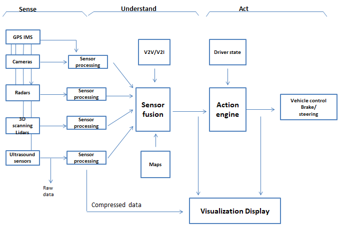
In general, a driver assistance system requires different sensors, an electronic control system in which Input devices such as sensors gather and respond to information and control a physical process by using electrical energy in the form of an output reaction. And the loudspeakers receive the control signals and displays to warn the actuators to actively intercede in the vehicle control system.
Current vehicle models are fitted with ultrasonic sensors which are used to measure the distance to the target by measuring the time between the emission and reception, basically used for parking assistance. Camera, Radar, and Lidar are the other sensors. Lidar similarly to radar sensors but emit light (light detection and ranging) Sensors continuously rotate and generate thousands of laser pulses per second. Automotive radars are used to perceive the speed and range of objects in the proximity of the car. The automotive radar consists of a receiver and a transmitter. The transmitter sends out radio waves that hit an object and bounce back to the receiver, determining the objects’ distance, speed and direction. Radar and lidar are very well suited for measuring distances between your vehicle and objects in the environment. Also, these sensors can be used to determine relative speeds.
All sensor data is evaluated in ECU. In a few vehicles, the steering wheel can also vibrate briefly, or a warning symbol appears on the speedometer display. In more complex systems some actuators intercede directly in the vehicle control system. In the meantime, Automatic Emergency Braking(AEB) assistance has become a legal requirement. The AEB system detects barricade, if the driver does not react in time, it automatically initiates emergency braking. Systems such as active lane departure warning or adaptive distance control, automatically control a vehicle’s speed and the steering angle.
Software is considered the backbone of hardware functions. The wiring of the actuation system in vehicles has been a major conciliator of ADAS. This allows many ADAS systems to function normally with other electrical components. The processors analyze the data from the ADAS system and vehicle sensors that can make the resulting decision achievable by actuators. The actuator system supports all starting from electric power steering to autonomous acceleration and breaking. In ADAS applications, processors are used for everything from building a real-time model of a car’s structure to proximity calculation and threat levels of the environment. The infrastructure and geographical information are collected, stored, and updated via sensors to direct a vehicle’s exact location. This information is managed and sent to the control system even if the GPS coverage fails.
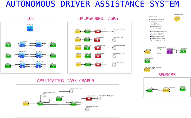
This Autonomous Driving Assistance System is built with 4 Radars, 6 cameras, and 2 Lidars connected to 12 ECUs, gateways, and IEEE802.1Q networks. The prototype is set up to quickly modify feature packages and hardware distribution to determine the hardware and network configuration. The response time for an active safety action is the primary criterion.
The below ADAS model is constructed using VisualSim Software:
The Graphs of the ADAS Model developed using VisualSim Software:
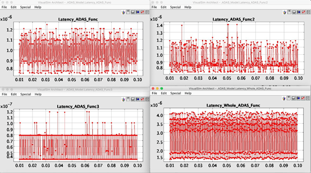

The latency observed at various stages of the model is shown in Figure 2. The “Latency ADAS function” graph shows the observed latency for the incoming data from the Position Sensor and the Spark Knock Sensor. Position sensors are used in automobiles to determine the steering wheel position, pedal positions, seat positions, and the position of various valves, knobs and actuators. Whereas a knock sensor is essentially a small “listening” device in or on the engine that detects these irregular vibrations and sounds that come from the engine block. The knock sensor picks up vibration and sound coming from the engine block, turns it into an electronic signal and sends that signal to the engine control unit (ECU). The car’s computer then judges the information and determines whether or not ignition timing should be altered.
The Latency ADAS function 2 graph shows the latency plots for the Coolant Temperature Sensor, Infrared Camera and the LIDAR whereas Latency ADAS function 3 graph depicts the latency observed in RADAR and the Vision Sensor. A coolant temperature sensor measures the temperature of the coolant mix in the cooling system, giving an indication of how much heat the engine is giving off. LIDAR, RADAR and Camera are the environment sensors central to the autonomous car operation. They used to detect and classify the objects around the car by location and velocity. Each of the sensors has limitations and the information obtained from them is fused together with confidence prior to making a decision on the vehicles trajectory.
VisualSim Architect – CAN_Node_Messages
CAN1_ECU3 Start_A rb0ther_0x006 0x603
DISPLAY AT TIME 99.7610000000 ms
CAN1_ECU4 Output 0ther_0x006 0x603
DISPLAY AT TIME 99.7740000000 ms
CANl_ECU5 Start_ArbBrake_0x016 0x605
DISPLAY AT TIME 99.7740000000 ms —
CAN1_ECU4 Start_ArbADAS_0x618 0x604
DISPLAY AT TIME 99.7740000000 ms —
CAN1_ECU3 Start_ArbOther_0x006 0x603
DISPLAY AT TIME — 99.8390000000 ms —
CAN1_ECU4 Output 0ther_0x006 0x603
DISPLAY AT TIME – 99.8520000000 ms –
CAN1_ECU5 Start_ArbBrake_0x016 0x605
DISPLAY AT TIME 99.8520000000 ms —
CAN1_ECU4 Start_ArbADAS_0x618 0x604
DISPLAY AT TIME 99.8520000000 ms
CANL_ECU3 Start_Arb0ther_0x006 0x603
DISPLAY AT TIME 99.9130000000 ms —
CAN1_ECU4 Output 0ther_0x006 0x603
DISPLAY AT TIME 99.9260000000 ms—
CAN1_ECU5 Start_ArbBrake_0x016 0x605
DISPLAY AT TIME – 99.9260000000 ms –
CAN1_ECU4 Start_ArbADAS_0x618 0x604
DISPLAY AT TIME 99.9260000000 ms—
CAN1_ECU3 Start_ArbOther_0x006 0x603
DISPLAY AT TIME — 99.9910000000 ms —
CAN1_ECU4 Output 0ther_0x006 0x603
Conclusion:
ADAS systems have the capacity to improve road safety across the globe. Today, ADAS is nearly conventional. Starting from the high-end models to the compact economy cars, they offer a wide array of facilities focusing on driver safety. With all the enhanced features and pleasure content that are available in a vehicle, the driver must still focus on driving. Sensor technology can help to keep a check on whether the driver is distracted or focused and sends the signal to the driver.
Have a question? Or perhaps you would like to know more?