AVB_Example_Model
Browsable image of the model.
- For an executable version,

- Mouse over the icons to view parameters. Click on hierarchy and plotters to reveal content (if provided).
- To simulate, click on Launch button, open downloaded file and click Run on the Java Security Page.
Introduction to the Audio-Video Bridging Library
Mirabilis Design provides an Audio-Video Bridging (AVB Library) as a standard add-on to the Ethernet and Networking application library in VisualSim Architect modeling environment. Using this environment, systems engineers and product architects can evaluate the impact of design decisions on the performance of their system. The AVB library has been built to the specification of the IEEE 802.1BA for time-synchronized low latency streaming services. The library supports the following standards:
- IEEE 802.1AS: Timing and Synchronization for Time-Sensitive Applications (gPTP),
- IEEE 802.1Qat: Stream Reservation Protocol (SRP),
- IEEE 802.1Qav: Forwarding and Queuing for Time-Sensitive Streams (FQTSS), and
- IEEE 802.1BA: Audio Video Bridging Systems
VisualSim AVB modeling environment supports the requirement of the automotive, consumer, and professional audio and video markets. Combined with the industry hardware, software and system library provided in VisualSim Architect, designers assemble an end-to-end system and evaluate the throughput, latency and other performance attributes. The proposed system can tested for various fault and error condition to evaluate the susceptibility of the system for real-world conditions.
VisualSim AVB can be used to design a completely new AVB-based network to integrate all the equipment, upgrade existing networks, and to design the electronics that are used in such networks. The AVB system can include the talkers and listeners such as video cameras, radars, broadcast systems, displays, and Electronic Control Units. The network can include AVB interfaces, bridges, switches and gateways.
Library
The AVB library is available as feature in VisualSim. The AVB library is located in Application->Networking->AVB.
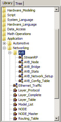
The library contains the six modeling blocks and the Ethernet Traffic block. The following blocks are located in the Application->Networking->AVB directory.
- StreamRP- This block manages the Talker_Advertise functionality at the Source Nodes. This is only required at the Source Nodes.
- AVB_Node- This block connects the AVB Node to the Network. It performs the AVB Reservation protocol, traffic shaping, and clock synchronization.
- AVB_Bridge- This block connects to both Nodes and other Bridges. It handles the Routing, traffic shaping, multicast, AVB stream reservation, and broadcast of clock synchronization messages to all the links. Note: The current implementation of the AVB Bridge can handle a maximum of eight (8) links only.
- AVB_Stats- This is a convenient block that displays the latency plot for all streams form all the Nodes, writes the information and warning messages to a file in the model directory, and computes the latency jitters and writes it to a separate file in the Model Directory.
- AVB_Network_Setup- One instance of this block is required in all AVB Models. This processes all the Tables in the model.
- AVB_Config_Tables- This is a block that contains the sample of all the configuration tables required for AVB.
- Ethernet_Traffic- This is a traffic generator that can handle both Ethernet traffic and AVB talker request message.
Tutorial System
Multiple demonstration systems are provided with documentation to guide a user to learn the AVB modeling environment and create executable models.
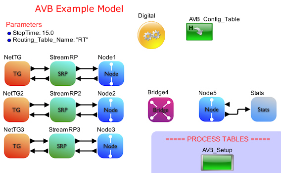
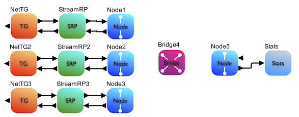
A demonstration system is provided with explanation on the use of this library. The block diagram is provided below:
Nodes 1, 2 and 3 are Talkers. Each Node has one Ethernet, three Class A streams and one Class B stream. All the Talkers transmit to a single Listener- Node 5. All the 4 Nodes are connected to a single Bridge 1.
The VisualSim model of this design is at- VS_AR/demo/networking/AVB/AVB_Example_System.xml.
Each node consists of one Ethernet_Traffic, StreamRP and Node block. The Bridge uses the AVB_Bridge block. As Node 5 is the Listener, the output of this block is connected to the AVB_Stats. The AVB_Network_Setup and the AVB_Config_Table are added to this block diagram to define the model attributes. The single parameter- Routing_Table_Name is to ensure that the Nodes, Bridges, AVB_Network_setup and the AVBP_Config_Table refer to the same Routing Table block. The Digital simulation is added with a stop time linked to both the Simulator and the AVB_Stats block.
When you run the simulation, there are four outputs. There are two plots- one displaying the latency for all the streams and the other is Histogram of the latency. There are two text files that are written at the end of the simulation- one contains information and warning messages, and the other contains the latency statistics for each stream.
Basic Rules
- All Sources and Destination must start with Node_ followed by a number
- All Bridges must start with Bridge_ followed by a number
- Each Traffic Generator will have a Traffic Table
- Bandwidth credit and Class type for all streams from all nodes are listed in a single Stream Table
- The AVB_Network_Setup must be present in all models using AVB.
- The AVB_Config_Table is only an example of the required Tables. The user must modify all the Tables to setup the required configuration. Additional Traffic Tables must be added to cover all the Nodes.
Construction Steps
To construct an AVB network model, there are five parts
- AVB Configuration Tables
- Pre-process block called AVB_Network_Setup
- Instantiate Nodes and Bridges
- Add the traffic and the Stream Reservation Protocol module for each Node.
- Attach the statistics block to each of the Nodes that are receiving data
a. Drag Application->Networking->AVB->AVB_Config_Table block into the Block Diagram Editor. This provides the list of sample Tables that are required for the AVB model.
b. The parameter- Routing_Table_Name value will be common to all the Node, Bridge, AVB_Network_Setup and to this block. Link this to the top-level Routing_Table_Name parameter.
c. Right-click on the block and select Open Block’ menu item
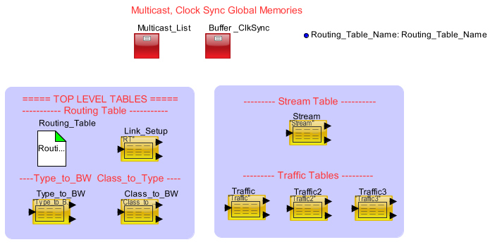
Figure 3 AVB Tables
d. There are eight common Tables.
i. Routing_Table- No change. This is a standard block in the Application->Networking library. This is required to handle the routing between nodes, compute the latency on the links and maintain statistics.
ii. Buffer_ClkSync- No change. Buffer_ClkSync is a Memory_Init block. This contains a set of required parameters for AVB. The following is the list of variables. Percent_BW global 0.75 ; ---Maximum allocation to Class A or B of the total bandwidth for that Type Max_Pkt_Bytes global 1500 ; ---Maximum packet size Max_Buffer_Pkts global 256 Maximum number of buffers at each Node. Each buffer can hold one Data Structure or packet Grand_Master global "Node_1" ; ---Node Name of the Master for the Clock Sync. Grand_Master_Rate global 200.0E-03 ; ---Rate of Clock Synchronization messages from the Grand Master Node
iii. Multicast_List- No change. Multicast_List is a Memory_Init block. This block contains all the information required for the Ethernet MAC ID Multicast IGMP protocol. The first row in this block has the name Multicast_List Global {List of Multicast} ;. The remaining rows contain the Destination Nodes list for each item in the Multicast list in Row 1. For each Row, the format will be ListName global {Node1, Node2} ;. The ListName must be Multicast_+Number. The number must be an increasing sequence and no number must be left out.
iv. Link_Setup- This table contains the attributes of each link in the network. This table is common to both AVB and non-AVB networks. The Linking_Table_Name of this block must match the name of the Routing_Table block. For each link in the model, define all the links with Source, Destination, Distance, Speed and Duplex (true).
| ID | Source_Node | Destination_Node | Distance | Speed_Mbps | Duplex ; |
| 1 | Node_1 | Bridge_4 | 1.0 | 100.0 | true ; |
| 2 | Node_2 | Bridge_4 | 1.0 | 100.0 | true ; |
| 3 | Node_3 | Bridge_4 | 1.0 | 100.0 | true ; |
| 4 | Bridge_4 | Node_5 | 1.0 | 100.0 | true ; |
Field Definitions:
ID; Increasing sequence number starting from 1.
Source_Node: Starting Node
Destination_Node: Ending Node of this link
Distance: Length of the link. The unit is defined by the Routing_Latency parameter of the Routing_Table block.
Speed_Mbps: Bandwidth of this link.
Duplex: This is an optional field. If true, then links in both directions with the same distance and speed.
v. Traffic_Table- One table is required for each Node. Enter the list of both AVB and Ethernet streams. One sample table is provided. Copy this instance to generate the required number of traffic tables. Make sure to give each Table a unique Name for the Linking_Table_Name. The list of all the Traffic_Tables must be provided to the AVB_Network_Setup block.
ID Identifier Task_Source Task_Destination Mbps Task_Size Start_Time Stop_Time Protocol Type ; 1 "00:01" Node_1 Node_5 2.0 128 10.0E-03 15.0 UDP 1 ; ID: Increasing sequence number Identifier: For Ethernet traffic, this field will be "Ethernet". For AVB streams, this will be any other value. Task_Source: Name of this Source Node. Task_Destination: Name of the final destination or listener. Mbps: Generation rate of this traffic stream Task_Size: Packet data size. Does not include headers or tailers Start_Time: Time in seconds after the start of the simulation Stop_Time: Time in seconds after the start of the simulation Protocol: UDP or TCP Type: Type of Class. Can be 0 to 7.vi. Stream- This table contains the Class and the requested bandwidth for all AVB stream from all the nodes.
ID Mac_ID Identifier SR_Class Mbps ; 1 "a0:36:9f:0c:77:38" "00:01" A 2.0 ; ID: Increaing sequence number MAC_ID: Physical address of the Node Identifier: Unique ID for each AVB stream. This must match the Identifier in the Traffic Table. SR_Class: Stream Reservation class of this AVB stream- A or B. Mbps: Requested bandwidthvii. Type_to_BW- For each Bridge and Node in the model, the amount of bandwidth allocated to each Type is specified in this Table. This table has two formats. It can have a single common column with the title Mbps or a separate column for each Node and Bridge in the model.
Common format is:| ID | Type | Mbps ; |
| 0 | 0 | 25.0 ; |
| 1 | 1 | 0.0 ; |
| 2 | 2 | 0.0 ; |
| 3 | 3 | 40.0 ; |
| 4 | 4 | 0.0 ; |
| 5 | 5 | 25.0 ; |
| 6 | 6 | 0.0 ; |
| 7 | 7 | 0.0 ; |
ID: Increasing sequence number starting from 1.
Type: Type of Class. The values are 0 to 7.
Mbps: Bandwidth allocation. The sum of all the rows of this column must not exceed the total bandwidth of the links.
Full-format is:| ID | Type | Node_1 | Node_2 | Node_3 | Bridge_4 | Node_5 ; |
| 0 | 0 | 25.0 | 25.0 | 25.0 | 25.0 | 25.0 ; |
| 1 | 1 | 0.0 | 0.0 | 0.0 | 0.0 | 10.0 ; |
| 2 | 2 | 0.0 | 0.0 | 0.0 | 0.0 | 0.0 ; |
| 3 | 3 | 40.0 | 40.0 | 40.0 | 40.0 | 40.0 ; |
| 4 | 4 | 0.0 | 0.0 | 0.0 | 0.0 | 0.0 ; |
| 5 | 5 | 25.0 | 25.0 | 25.0 | 20.0 | 25.0 ; |
| 6 | 6 | 0.0 | 0.0 | 0.0 | 0.0 | 0.0 ; |
| 7 | 7 | 0.0 | 0.0 | 0.0 | 0.0 | 0.0 ; |
ID: Increasing sequence number starting from 1.
Type: Type of Class. The values are 0 to 7.
Node_1, Bridge_1...: Bandwidth allocation. The sum of all the rows of each column must not exceed the total bandwidth of the link.
viii. Class_to_Type- For each Bridge and Node in the model, the mapping of Type to Class and B. This Table also has two formats.
Common Format: ID Class Type ; 0 A 5 ; 1 B 3 ;ID: Increasing sequence number starting from 1
Class: A or B
Type: Type of Class. The values are 0 to 7. Common to all Nodes and Bridges in the model.
Full-Format: ID Class Node_1 Node_2 Node_3 Bridge_4 Node_5 ; 0 A 5 5 5 5 5 ; 1 B 3 3 3 3 3 ;ID: Increasing sequence number starting from 1.
Class: First Row is A and the second row is B.
Node_1, Bridge_1...: Type for Class A and B.
Step 2:In this step we add the block required for Pre-processing the tables. This block must be added to all AVB models or models that use the AVB blocks. This block does require the existence of the Traffic tables, Routing Table, Link Setup table, Type_to_BW table, Class_to_Type table and Multicast Memory_Init block.
a. Instantiate the Application->Networking->AVB->AVB_Setup block.
b. Link the Routing_Table_Name parameter to the top-level. This ensures that all blocks will use the same name.
c. In the parameter ‘List_of_Tables’, list all the traffic tables names as strings in array.
Step 3:Each transmitting node (Source or Talker) requires three blocks- Ethernet_Traffic, StreamRP and Node block. The assembly of the three blocks is as follows.
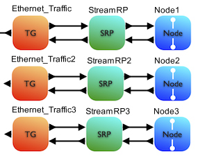
Figure 4 Assembly of the Source Node
A Receiver-only does not require Ether_Traffic and StreamRP. Each Receiver node (Listener or Destination) requires only the Node block. If statistics is required at this block, then the AVB_Stats block must be added on the output. For more details on AVB_Stats, review Step 5.
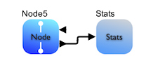
Figure 5 Assembly of a Destination-only Node
Some blocks will be both Source and Destination. In this case the Stats must be connected to the data_out of the Ethernet_Traffic block. To learn more about the AVB_Stats, look at the Step 5.
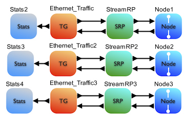
Figure 6 Node is both a Source and Destination
The following is the sequence.
a. Add as many Application->Networking->AVB->AVB_Node block as specified in the Link Configuration table.
b. Assign a unique name. The rule here is that the name must be Node_ followed by a number. No two Nodes can have the same.
c. Link the Routing_Table_Name with the parameter at the top-level.
d. Each Source Node block will be connected an Application->Networking->Network_Traffic_Generator block connected to a Application->Networking->AVB->AVB_SRP which is connected to the Application->networking->AVB->AVB_Node block. The AVB_Stats block will only be attached to a Destination block. A Destination-only block will have the AVB_Stats block attached to the Node block output. A Node that is both Source and Destination will have the AVB_Stats connected to the data_out port of the Ethernet_Traffic block.
Step 4:The Bridge connects the Nodes to the network and also connects to other Bridges. The bridge block handles the Routing, broadcast of clock synchronization, AVB stream reservation and traffic shaping. A maximum of 8 links can be connected to a Bridge block. These can be any combination of Bridges and Nodes.
A model can have a single bridge with all the Nodes connected to it.
ID Source_Node Destination_Node Distance Speed_Mbps Duplex ; |
Figure 7 Single Bridge Network
If a model has multiple bridges, instantiate as many AVB_Bridge blocks and update the Link_Setup. The topology of the network is determined by the Link_Setup table. The Block Diagram shows the number of Bridge and Node instances.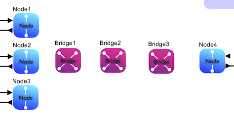
ID Source_Node Destination_Node Distance Speed_Mbps Duplex ; |
Figure 8 Many Bridge Network
The following is the sequence:
a. Add as many Application->Networking->AVB->AVB_Bridge blocks as you have defined in the Link Configuration table
b. Assign a unique name to each Bridge block. The rule here is that the name must be Bridge_ followed by a number. No two Bridges can have the same
c. For the parameter, add the Routing_Table_Name. For now it is just “RT”.
Step 5:The AVB_Stats block can be connected directly to the Node out for a Destination-only or the data_out port of the Ethernet_Traffic block for a Source+Destination block.
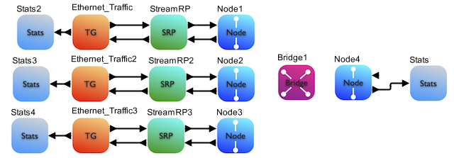
Figure 9 Connecting the Statistics block to the Node
The AVB_Stats generates 4 different pieces of information. They are: 1. The latency statistics for all the streams arriving at Node to which this AVB_Stats is connected.Ethernet Stream |
AVB Stream |
N1_to_N4- Node_1 to Node_4
Ether_1- Ethernet stream with ID 1 in the Traffic Table
Stream_7- 07 is the Stream Identifier in the stream table and the Traffic Table
Minimum- Lowest latency recorded during the simulation
Maximum- Highest latency recorded during the simulation
Mean- Average of all the latencies recorded
Std Dev- Standard Deviation of the latencies
2. The activity during the simulation including the Talker Advertise, Listener Ready, Talker Failed, Deregister, Stream Reservation protocol loop activity and data transfer rate.
Stream 00:05 at Node 2 issues Talker Advertise message to the Node. Stream 00:07 of type Class B failed to get bandwidth credit at Bridge_2 with failure Code 3 Stream 00:05 of Node_2 of type class A received a Listener ready and will start transmitting. Stream 00:08 of Node_2 has stopped transmitting. Stream 00:08 of Node_2 has deregisted on the Network. |
3. Graphical plot showing the Latency for all the streams arriving at the Node to which this AVB_Stats block is connected.
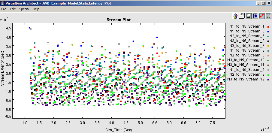
Figure 10 Stream Latency Plot
Here N2_to_N4_Stream_7- Means Node_2 to Node_4 for stream 7. The color in the reference will match the color in the plot.
4. Histogram of the Latency for all the streams arriving at the Node to which this AVB_Stats block is connected.
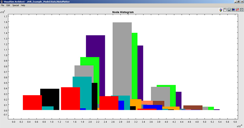
Figure 11 Histogram of the Stream Latencies
Here N2_to_N4_Stream_7- Means Node_2 to Node_4 for stream 7. The color in the reference will match the color in the plot.
The following is the connection sequence:
a. Connect an Application->Networking->AVB->AVB_Stats block to the output of each of the Nodes. This will capture all the statistics including the activity traces, latency and histogram plots. You can see a unique latency graph at each Listener of Destination Node. We only need this block for Nodes that will receive data.
b. Enter the name of the Node that this block is connected and set the ending time of the simulation.
Step 6:Now the model has been constructed. The next step is to run the simulation. Each simulation run can have different setup values- such as Network Toplogy (Link_Setup file), traffic streams from each node (Traffic table), number of AVB streams (stream table) and allocation of bandwidth to each Type at each Bridge (Type_to_BW).
For each run, the statistics are provided in a combination of files and graphical plots. View Step 5 to see the list of plots and reports.