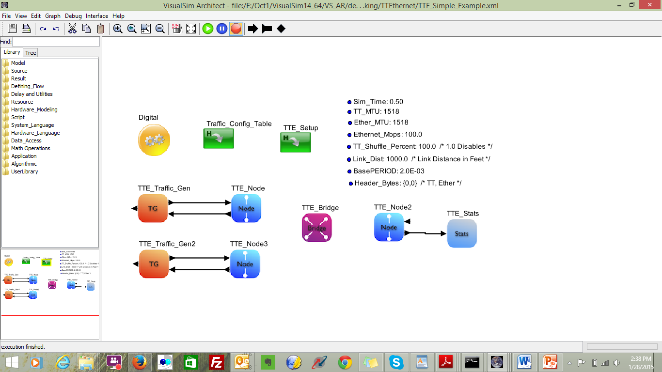
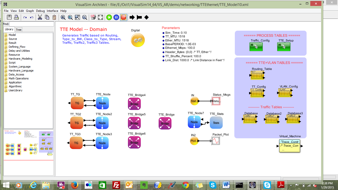
Time-Triggered Ethernet

Models a large scale automotive network with multiple CAN, Can-FD buses, Gateways and Ethernet interfaces. Support for Idle Slope, Send Slope, Control Gate, preemption, Message and Signal Routing, Clock Synchronization

TTE_Model

Browsable image of the model.

  • For an executable version,
  • Mouse over the icons to view parameters. Click on hierarchy and plotters to reveal content (if provided).
  • To simulate, click on Launch button, open downloaded file and click Run on the Java Security Page.
TTE_Modelmodel <h2>TextDisplay</h2><table border="1"><tr><td><b>Parameter</b></td><td><b>Expression</b></td><td><b>Value</b></td></tr><tr><td>Block_Documentation</td><td>Enter User Documentation Here</td><td>Enter User Documentation Here</td></tr><tr><td>rowsDisplayed</td><td>10</td><td>10</td></tr><tr><td>columnsDisplayed</td><td>40</td><td>40</td></tr><tr><td>suppressBlankLines</td><td>false</td><td>false</td></tr><tr><td>title</td><td>&quot;Status_Msg&quot;</td><td>&quot;Status_Msg&quot;</td></tr><tr><td>ViewText</td><td>true</td><td>true</td></tr><tr><td>saveText</td><td>false</td><td>false</td></tr><tr><td>fileName</td><td>Enter Filename to save text</td><td>&quot;Enter Filename to save text&quot;</td></tr><tr><td>Append_Time</td><td>true</td><td>true</td></tr></table> <h2>DS_xTime_yData_Plotter</h2><table border="1"><tr><td><b>Parameter</b></td><td><b>Expression</b></td><td><b>Value</b></td></tr><tr><td>Block_Documentation</td><td>Enter User Documentation Here</td><td>Enter User Documentation Here</td></tr><tr><td>fillOnWrapup</td><td>true</td><td>true</td></tr><tr><td>legend</td><td>&nbsp;</td><td>&nbsp;</td></tr><tr><td>startingDataset</td><td>0</td><td>0</td></tr><tr><td>fileName</td><td>Enter Filename to save plot</td><td>&quot;Enter Filename to save plot&quot;</td></tr><tr><td>Field_Trace_Name</td><td>&quot;Plot_Name&quot;</td><td>&quot;&quot;Plot_Name&quot;&quot;</td></tr><tr><td>Field_Y_Value</td><td>input.Plot_Value</td><td>&quot;input.Plot_Value&quot;</td></tr><tr><td>Field_Color</td><td>&quot;Plot_Color&quot;</td><td>&quot;&quot;Plot_Color&quot;&quot;</td></tr><tr><td>Field_Offset</td><td>&quot;Plot_Offset&quot;</td><td>&quot;&quot;Plot_Offset&quot;&quot;</td></tr><tr><td>viewPlot</td><td>true</td><td>true</td></tr><tr><td>savePlot</td><td>false</td><td>false</td></tr></table> <h2>IN2</h2><table border="1"><tr><td><b>Parameter</b></td><td><b>Expression</b></td><td><b>Value</b></td></tr><tr><td>Block_Documentation</td><td>Enter User Documentation Here</td><td>Enter User Documentation Here</td></tr><tr><td>Destination_Name</td><td>Plotter</td><td>&quot;Plotter&quot;</td></tr><tr><td>Destination_Type</td><td>Global</td><td>Global</td></tr></table> <h2>TTE_Stats</h2><table border="1"><tr><td><b>Parameter</b></td><td><b>Expression</b></td><td><b>Value</b></td></tr><tr><td>_explanation</td><td>Interfaces and Buses-&gt;TimeTriggeredEthernet-&gt;TTE_Stats</td><td>Interfaces and Buses-&gt;TimeTriggeredEthernet-&gt;TTE_Stats</td></tr><tr><td>Node_Name</td><td>&quot;Node_6&quot;</td><td>&quot;Node_6&quot;</td></tr><tr><td>Second_Plot_Contains</td><td>{&quot;N1&quot;,&quot;Stream_1&quot;} /* AND conditions */</td><td>{&quot;N1&quot;, &quot;Stream_1&quot;}</td></tr><tr><td>Enable_Write_to_File</td><td>false</td><td>false</td></tr><tr><td>Enable_Second_Plot</td><td>false</td><td>false</td></tr><tr><td>Enable_Histogram</td><td>false</td><td>false</td></tr></table> <h2>Database3</h2><table border="1"><tr><td><b>Parameter</b></td><td><b>Expression</b></td><td><b>Value</b></td></tr><tr><td>Block_Documentation</td><td>Mac_ID     :: Mac_ID Address   Mbps       :: Data rate\\nSize_Bytes :: 1500             Start_Time :: 0.0    \\nStop_Time  :: 1.0E-03          Protocol   :: TCP_IP or UDP</td><td>Mac_ID     :: Mac_ID Address   Mbps       :: Data rate\\nSize_Bytes :: 1500             Start_Time :: 0.0    \\nStop_Time  :: 1.0E-03          Protocol   :: TCP_IP or UDP</td></tr><tr><td>Linking_Name</td><td>&quot;Traffic3&quot;</td><td>&quot;Traffic3&quot;</td></tr><tr><td>fileOrURL</td><td>&nbsp;</td><td>&quot;&quot;</td></tr><tr><td>Data_Structure_Text</td><td>/* Text Template or File Path.       \\n   First row contains Field Names.    */\\nID Identifier  Task_Source  Task_Destination  Mbps  Task_Size  Start_Time  Stop_Time  Protocol VLAN Type ;       \\n 1 &quot;TT3&quot;       Node_3       Node_6         \t25.0   192    0.0        0.5      UDP    9    7  ; \\n/* 2 &quot;RC5&quot;       Node_3       Node_6             0.5         64    10.5E-03        0.5      UDP   10    6  ; \\n 3 &quot;RC6&quot;       Node_3       Node_6             0.5        128    11.0E-03        0.5      UDP   11    6  ; \\n 4 &quot;Ethernet&quot;  Node_3       Node_6             0.3         64    11.5E-03        0.5      UDP   12    5  ;  */</td><td>/* Text Template or File Path.       \\n   First row contains Field Names.    */\\nID Identifier  Task_Source  Task_Destination  Mbps  Task_Size  Start_Time  Stop_Time  Protocol VLAN Type ;       \\n 1 &quot;TT3&quot;       Node_3       Node_6         \t25.0   192    0.0        0.5      UDP    9    7  ; \\n/* 2 &quot;RC5&quot;       Node_3       Node_6             0.5         64    10.5E-03        0.5      UDP   10    6  ; \\n 3 &quot;RC6&quot;       Node_3       Node_6             0.5        128    11.0E-03        0.5      UDP   11    6  ; \\n 4 &quot;Ethernet&quot;  Node_3       Node_6             0.3         64    11.5E-03        0.5      UDP   12    5  ;  */</td></tr><tr><td>Input_Fields</td><td>&quot;ID&quot;</td><td>&quot;ID&quot;</td></tr><tr><td>Lookup_Fields</td><td>&quot;ID&quot;</td><td>&quot;ID&quot;</td></tr><tr><td>Output_Expression</td><td>&quot;output = match&quot; /* FORMAT output = match.fieldb */</td><td>&quot;output = match&quot;</td></tr><tr><td>Mode</td><td>Read</td><td>Read</td></tr><tr><td>TT_Bytes</td><td>64</td><td>64</td></tr><tr><td>TT_Mbps</td><td>(1.0E-6*TT_Bytes/BasePERIOD)</td><td>0.032</td></tr></table> <h2>Database2</h2><table border="1"><tr><td><b>Parameter</b></td><td><b>Expression</b></td><td><b>Value</b></td></tr><tr><td>Block_Documentation</td><td>Mac_ID     :: Mac_ID Address   Mbps       :: Data rate\\nSize_Bytes :: 1500             Start_Time :: 0.0    \\nStop_Time  :: 1.0E-03          Protocol   :: TCP_IP or UDP</td><td>Mac_ID     :: Mac_ID Address   Mbps       :: Data rate\\nSize_Bytes :: 1500             Start_Time :: 0.0    \\nStop_Time  :: 1.0E-03          Protocol   :: TCP_IP or UDP</td></tr><tr><td>Linking_Name</td><td>&quot;Traffic2&quot;</td><td>&quot;Traffic2&quot;</td></tr><tr><td>fileOrURL</td><td>&nbsp;</td><td>&quot;&quot;</td></tr><tr><td>Data_Structure_Text</td><td>/* Text Template or File Path.       \\n   First row contains Field Names.    */\\nID Identifier  Task_Source  Task_Destination  Mbps  Task_Size  Start_Time  Stop_Time  Protocol VLAN Type ;       \\n 1 &quot;TT2&quot;       Node_2       Node_6         15.0   128     0.0        0.5      UDP    5   7  ; \\n/* 2 &quot;RC3&quot;       Node_2       Node_6             0.5        128     2.0E-03        0.5      UDP    6   6  ; \\n 3 &quot;RC4&quot;       Node_2       Node_6             0.5         64     2.5E-03        0.5      UDP    7   6  ; \\n 4 &quot;Ethernet&quot;  Node_2       Node_6             0.3         64     3.0E-03        0.5      UDP    8   5  ; */</td><td>/* Text Template or File Path.       \\n   First row contains Field Names.    */\\nID Identifier  Task_Source  Task_Destination  Mbps  Task_Size  Start_Time  Stop_Time  Protocol VLAN Type ;       \\n 1 &quot;TT2&quot;       Node_2       Node_6         15.0   128     0.0        0.5      UDP    5   7  ; \\n/* 2 &quot;RC3&quot;       Node_2       Node_6             0.5        128     2.0E-03        0.5      UDP    6   6  ; \\n 3 &quot;RC4&quot;       Node_2       Node_6             0.5         64     2.5E-03        0.5      UDP    7   6  ; \\n 4 &quot;Ethernet&quot;  Node_2       Node_6             0.3         64     3.0E-03        0.5      UDP    8   5  ; */</td></tr><tr><td>Input_Fields</td><td>&quot;ID&quot;</td><td>&quot;ID&quot;</td></tr><tr><td>Lookup_Fields</td><td>&quot;ID&quot;</td><td>&quot;ID&quot;</td></tr><tr><td>Output_Expression</td><td>&quot;output = match&quot; /* FORMAT output = match.fieldb */</td><td>&quot;output = match&quot;</td></tr><tr><td>Mode</td><td>Read</td><td>Read</td></tr><tr><td>TT_Bytes</td><td>64</td><td>64</td></tr><tr><td>TT_Mbps</td><td>(1.0E-6*TT_Bytes/BasePERIOD)</td><td>0.032</td></tr></table> <h2>Database</h2><table border="1"><tr><td><b>Parameter</b></td><td><b>Expression</b></td><td><b>Value</b></td></tr><tr><td>Block_Documentation</td><td>Mac_ID     :: Mac_ID Address   Mbps       :: Data rate\\nSize_Bytes :: 1500             Start_Time :: 0.0    \\nStop_Time  :: 1.0E-03          Protocol   :: TCP_IP or UDP</td><td>Mac_ID     :: Mac_ID Address   Mbps       :: Data rate\\nSize_Bytes :: 1500             Start_Time :: 0.0    \\nStop_Time  :: 1.0E-03          Protocol   :: TCP_IP or UDP</td></tr><tr><td>Linking_Name</td><td>&quot;Traffic&quot;</td><td>&quot;Traffic&quot;</td></tr><tr><td>fileOrURL</td><td>&nbsp;</td><td>&quot;&quot;</td></tr><tr><td>Data_Structure_Text</td><td>/* Text Template or File Path.       \\n   First row contains Field Names.    */\\nID Identifier  Task_Source  Task_Destination  Mbps  Task_Size  Start_Time  Stop_Time  Protocol VLAN Type ;       \\n 1 &quot;TT1&quot;       Node_1       Node_6         10.0   \t64     0.0            0.5      UDP    1    7  ; \\n/* 2 &quot;RC1&quot;       Node_1       Node_6             0.5         64     1.5E-03        0.5      UDP    2    6  ; \\n 3 &quot;RC2&quot;       Node_1       Node_6             0.5        128     2.0E-03        0.5      UDP    3    6  ; \\n 4 &quot;Ethernet&quot;  Node_1       Node_6             0.3         64     2.5E-03        0.5      UDP    4    5  ;  */</td><td>/* Text Template or File Path.       \\n   First row contains Field Names.    */\\nID Identifier  Task_Source  Task_Destination  Mbps  Task_Size  Start_Time  Stop_Time  Protocol VLAN Type ;       \\n 1 &quot;TT1&quot;       Node_1       Node_6         10.0   \t64     0.0            0.5      UDP    1    7  ; \\n/* 2 &quot;RC1&quot;       Node_1       Node_6             0.5         64     1.5E-03        0.5      UDP    2    6  ; \\n 3 &quot;RC2&quot;       Node_1       Node_6             0.5        128     2.0E-03        0.5      UDP    3    6  ; \\n 4 &quot;Ethernet&quot;  Node_1       Node_6             0.3         64     2.5E-03        0.5      UDP    4    5  ;  */</td></tr><tr><td>Input_Fields</td><td>&quot;ID&quot;</td><td>&quot;ID&quot;</td></tr><tr><td>Lookup_Fields</td><td>&quot;ID&quot;</td><td>&quot;ID&quot;</td></tr><tr><td>Output_Expression</td><td>&quot;output = match&quot; /* FORMAT output = match.fieldb */</td><td>&quot;output = match&quot;</td></tr><tr><td>Mode</td><td>Read</td><td>Read</td></tr><tr><td>TT_Bytes</td><td>64</td><td>64</td></tr><tr><td>TT_Mbps</td><td>(1.0E-6*TT_Bytes/BasePERIOD)</td><td>0.032</td></tr></table> <h2>Routing_Table</h2><table border="1"><tr><td><b>Parameter</b></td><td><b>Expression</b></td><td><b>Value</b></td></tr><tr><td>Block_Documentation</td><td>*.xml, *.csv files abs or rel (./) path\\n  -- *.csv real columns set to number\\nInput_Fields == Lookup_Fields (num, type)\\nOutput_Expr: match, match_last, match_all\\n  -- match_all.field not allowed</td><td>*.xml, *.csv files abs or rel (./) path\\n  -- *.csv real columns set to number\\nInput_Fields == Lookup_Fields (num, type)\\nOutput_Expr: match, match_last, match_all\\n  -- match_all.field not allowed</td></tr><tr><td>Linking_Name</td><td>&quot;RT&quot;</td><td>&quot;RT&quot;</td></tr><tr><td>fileOrURL</td><td>&nbsp;</td><td>&quot;&quot;</td></tr><tr><td>Data_Structure_Text</td><td>/* Text Template or File Path.       \\n   First row contains Field Names. */\\nID Source_Node    Destination_Node  Distance  Speed_Mbps  Duplex   ;       \\n 1 Node_1         Bridge_4          Link_Dist      100.0    true   ; \\n 2 Node_2         Bridge_4          Link_Dist      100.0    true   ; \\n 3 Node_3         Bridge_4          Link_Dist      100.0    true   ; \\n 4 Bridge_4       Bridge_5          Link_Dist      100.0    true   ;\\n 4 Bridge_5       Node_6            Link_Dist      100.0    true   ;</td><td>/* Text Template or File Path.       \\n   First row contains Field Names. */\\nID Source_Node    Destination_Node  Distance  Speed_Mbps  Duplex   ;       \\n 1 Node_1         Bridge_4          Link_Dist      100.0    true   ; \\n 2 Node_2         Bridge_4          Link_Dist      100.0    true   ; \\n 3 Node_3         Bridge_4          Link_Dist      100.0    true   ; \\n 4 Bridge_4       Bridge_5          Link_Dist      100.0    true   ;\\n 4 Bridge_5       Node_6            Link_Dist      100.0    true   ;</td></tr><tr><td>Input_Fields</td><td>&quot;Source_Node&quot;</td><td>&quot;Source_Node&quot;</td></tr><tr><td>Lookup_Fields</td><td>&quot;Source_Node&quot;</td><td>&quot;Source_Node&quot;</td></tr><tr><td>Output_Expression</td><td>&quot;output = match&quot; /* FORMAT output = match.fieldb */</td><td>&quot;output = match&quot;</td></tr><tr><td>Mode</td><td>Read</td><td>Read</td></tr></table> <h2>TT_TG3</h2><table border="1"><tr><td><b>Parameter</b></td><td><b>Expression</b></td><td><b>Value</b></td></tr><tr><td>_explanation</td><td>Interfaces and Buses-&gt;TimeTriggeredEthernet-&gt;TTE_Traffic</td><td>Interfaces and Buses-&gt;TimeTriggeredEthernet-&gt;TTE_Traffic</td></tr><tr><td>Traffic_Table</td><td>&quot;Traffic3&quot;</td><td>&quot;Traffic3&quot;</td></tr></table> <h2>TT_TG2</h2><table border="1"><tr><td><b>Parameter</b></td><td><b>Expression</b></td><td><b>Value</b></td></tr><tr><td>_explanation</td><td>Interfaces and Buses-&gt;TimeTriggeredEthernet-&gt;TTE_Traffic</td><td>Interfaces and Buses-&gt;TimeTriggeredEthernet-&gt;TTE_Traffic</td></tr><tr><td>Traffic_Table</td><td>&quot;Traffic2&quot;</td><td>&quot;Traffic2&quot;</td></tr></table> <h2>TT_TG</h2><table border="1"><tr><td><b>Parameter</b></td><td><b>Expression</b></td><td><b>Value</b></td></tr><tr><td>_explanation</td><td>Interfaces and Buses-&gt;TimeTriggeredEthernet-&gt;TTE_Traffic</td><td>Interfaces and Buses-&gt;TimeTriggeredEthernet-&gt;TTE_Traffic</td></tr><tr><td>Traffic_Table</td><td>&quot;Traffic&quot;</td><td>&quot;Traffic&quot;</td></tr></table> <h2>VLAN_Config</h2><table border="1"><tr><td><b>Parameter</b></td><td><b>Expression</b></td><td><b>Value</b></td></tr><tr><td>Block_Documentation</td><td>Enter User Documentation Here</td><td>Enter User Documentation Here</td></tr><tr><td>Linking_Name</td><td>&quot;VLAN&quot;</td><td>&quot;VLAN&quot;</td></tr><tr><td>fileOrURL</td><td>&nbsp;</td><td>&quot;&quot;</td></tr><tr><td>Data_Structure_Text</td><td>/* Text Template or File Path.       \\n   First row contains Field Names. */\\nID VLAN  BAG  \t\tLMax  ;       \\n 1   1   1.0e-6    \t256   ; \\n 2   2   1.5e-6 \t512   ; \\n 3   3   2.0e-6   \t1024  ; \\n 4   4   2.0e-6   \t1024  ; \\n 5   5   2.0e-6\t\t1024  ;\\n 6   6   2.0e-6\t\t1024  ;\\n 7   7   2.0e-6\t\t1024  ;\\n 8   8   2.0e-6\t\t1024  ;\\n 9   9   2.0e-6\t\t1024  ;\\n 10  10  2.0e-6\t\t1024  ;\\n 11  11  2.0e-6\t\t1024  ;\\n 12  12  2.0e-6\t\t1024  ;\\n 13  13  2.0e-6\t\t1024  ;\\n 14  14  2.0e-6\t\t1024  ;\\n 15  15  1.0e-6    \t256   ; \\n 16  16  1.5e-6   \t512   ; \\n 17  17  2.0e-6   \t1024  ; \\n 18  18  2.0e-6   \t1024  ; \\n 19  19  2.0e-6\t\t1024  ;\\n 20  20  2.0e-6\t\t1024  ;\\n 21  21  2.0e-6\t\t1024  ;\\n 22  22  2.0e-6\t\t1024  ;\\n 23  23  2.0e-6\t\t1024  ;\\n 24  24  2.0e-6\t\t1024  ;\\n 25  25  2.0e-6\t\t1024  ;\\n 26  26  2.0e-6\t\t1024  ;\\n 27  27  2.0e-6\t\t1024  ;\\n 28  28  2.0e-6\t\t1024  ;\\n 29  29  2.0e-6\t\t1024  ;\\n 30  30  2.0e-6\t\t1024  ;</td><td>/* Text Template or File Path.       \\n   First row contains Field Names. */\\nID VLAN  BAG  \t\tLMax  ;       \\n 1   1   1.0e-6    \t256   ; \\n 2   2   1.5e-6 \t512   ; \\n 3   3   2.0e-6   \t1024  ; \\n 4   4   2.0e-6   \t1024  ; \\n 5   5   2.0e-6\t\t1024  ;\\n 6   6   2.0e-6\t\t1024  ;\\n 7   7   2.0e-6\t\t1024  ;\\n 8   8   2.0e-6\t\t1024  ;\\n 9   9   2.0e-6\t\t1024  ;\\n 10  10  2.0e-6\t\t1024  ;\\n 11  11  2.0e-6\t\t1024  ;\\n 12  12  2.0e-6\t\t1024  ;\\n 13  13  2.0e-6\t\t1024  ;\\n 14  14  2.0e-6\t\t1024  ;\\n 15  15  1.0e-6    \t256   ; \\n 16  16  1.5e-6   \t512   ; \\n 17  17  2.0e-6   \t1024  ; \\n 18  18  2.0e-6   \t1024  ; \\n 19  19  2.0e-6\t\t1024  ;\\n 20  20  2.0e-6\t\t1024  ;\\n 21  21  2.0e-6\t\t1024  ;\\n 22  22  2.0e-6\t\t1024  ;\\n 23  23  2.0e-6\t\t1024  ;\\n 24  24  2.0e-6\t\t1024  ;\\n 25  25  2.0e-6\t\t1024  ;\\n 26  26  2.0e-6\t\t1024  ;\\n 27  27  2.0e-6\t\t1024  ;\\n 28  28  2.0e-6\t\t1024  ;\\n 29  29  2.0e-6\t\t1024  ;\\n 30  30  2.0e-6\t\t1024  ;</td></tr><tr><td>Input_Fields</td><td>&quot;ID&quot;</td><td>&quot;ID&quot;</td></tr><tr><td>Lookup_Fields</td><td>&quot;ID&quot;</td><td>&quot;ID&quot;</td></tr><tr><td>Output_Expression</td><td>&quot;output = match_all&quot; /* FORMAT output = match.fieldb */</td><td>&quot;output = match_all&quot;</td></tr><tr><td>Mode</td><td>Read</td><td>Read</td></tr></table> <h2>TTE_Node6</h2><table border="1"><tr><td><b>Parameter</b></td><td><b>Expression</b></td><td><b>Value</b></td></tr><tr><td>_explanation</td><td>Interfaces and Buses-&gt;TimeTriggeredEthernet-&gt;TTE_Node</td><td>Interfaces and Buses-&gt;TimeTriggeredEthernet-&gt;TTE_Node</td></tr><tr><td>Node_Name</td><td>&quot;Node_6&quot;</td><td>&quot;Node_6&quot;</td></tr><tr><td>Synchronization_Master</td><td>false</td><td>false</td></tr><tr><td>Redundant_Nodes</td><td>1  /* 1,2,3 */</td><td>1</td></tr><tr><td>_flipPortsVertical</td><td>true</td><td>true</td></tr><tr><td>_flipPortsHorizontal</td><td>false</td><td>false</td></tr><tr><td>_rotatePorts</td><td>180</td><td>180</td></tr></table> <h2>TTE_Node3</h2><table border="1"><tr><td><b>Parameter</b></td><td><b>Expression</b></td><td><b>Value</b></td></tr><tr><td>_explanation</td><td>Interfaces and Buses-&gt;TimeTriggeredEthernet-&gt;TTE_Node</td><td>Interfaces and Buses-&gt;TimeTriggeredEthernet-&gt;TTE_Node</td></tr><tr><td>Node_Name</td><td>&quot;Node_3&quot;</td><td>&quot;Node_3&quot;</td></tr><tr><td>Synchronization_Master</td><td>false</td><td>false</td></tr><tr><td>Redundant_Nodes</td><td>1  /* 1,2,3 */</td><td>1</td></tr></table> <h2>TTE_Node2</h2><table border="1"><tr><td><b>Parameter</b></td><td><b>Expression</b></td><td><b>Value</b></td></tr><tr><td>_explanation</td><td>Interfaces and Buses-&gt;TimeTriggeredEthernet-&gt;TTE_Node</td><td>Interfaces and Buses-&gt;TimeTriggeredEthernet-&gt;TTE_Node</td></tr><tr><td>Node_Name</td><td>&quot;Node_2&quot;</td><td>&quot;Node_2&quot;</td></tr><tr><td>Synchronization_Master</td><td>false</td><td>false</td></tr><tr><td>Redundant_Nodes</td><td>1  /* 1,2,3 */</td><td>1</td></tr></table> <h2>TTE_Node</h2><table border="1"><tr><td><b>Parameter</b></td><td><b>Expression</b></td><td><b>Value</b></td></tr><tr><td>_explanation</td><td>Interfaces and Buses-&gt;TimeTriggeredEthernet-&gt;TTE_Node</td><td>Interfaces and Buses-&gt;TimeTriggeredEthernet-&gt;TTE_Node</td></tr><tr><td>Node_Name</td><td>&quot;Node_1&quot;</td><td>&quot;Node_1&quot;</td></tr><tr><td>Synchronization_Master</td><td>false</td><td>false</td></tr><tr><td>Redundant_Nodes</td><td>1  /* 1,2,3 */</td><td>1</td></tr></table> <h2>TTE_Bridge5</h2><table border="1"><tr><td><b>Parameter</b></td><td><b>Expression</b></td><td><b>Value</b></td></tr><tr><td>_explanation</td><td>Interfaces and Buses-&gt;TimeTriggeredEthernet-&gt;TTE_Bridge</td><td>Interfaces and Buses-&gt;TimeTriggeredEthernet-&gt;TTE_Bridge</td></tr><tr><td>Bridge_Name</td><td>&quot;Bridge_5&quot;</td><td>&quot;Bridge_5&quot;</td></tr><tr><td>Compression_Master</td><td>true</td><td>true</td></tr><tr><td>Routing_Table_Name</td><td>&quot;RT&quot;</td><td>&quot;RT&quot;</td></tr><tr><td>Number_Ports</td><td>16</td><td>16</td></tr></table> <h2>TTE_Bridge4</h2><table border="1"><tr><td><b>Parameter</b></td><td><b>Expression</b></td><td><b>Value</b></td></tr><tr><td>_explanation</td><td>Interfaces and Buses-&gt;TimeTriggeredEthernet-&gt;TTE_Bridge</td><td>Interfaces and Buses-&gt;TimeTriggeredEthernet-&gt;TTE_Bridge</td></tr><tr><td>Bridge_Name</td><td>&quot;Bridge_4&quot;</td><td>&quot;Bridge_4&quot;</td></tr><tr><td>Compression_Master</td><td>true</td><td>true</td></tr><tr><td>Routing_Table_Name</td><td>&quot;RT&quot;</td><td>&quot;RT&quot;</td></tr><tr><td>Number_Ports</td><td>16</td><td>16</td></tr></table> <h2>IN</h2><table border="1"><tr><td><b>Parameter</b></td><td><b>Expression</b></td><td><b>Value</b></td></tr><tr><td>Block_Documentation</td><td>Enter User Documentation Here</td><td>Enter User Documentation Here</td></tr><tr><td>Destination_Name</td><td>Status_Msg</td><td>&quot;Status_Msg&quot;</td></tr><tr><td>Destination_Type</td><td>Global</td><td>Global</td></tr></table> <h2>TT_Config</h2><table border="1"><tr><td><b>Parameter</b></td><td><b>Expression</b></td><td><b>Value</b></td></tr><tr><td>Block_Documentation</td><td>TTName     : Traffic Tables as MacID Identifier\\nStartTime  : Start of Slot     (sec)\\nBasePeriod : Repeat Rate       (sec)\\nProcTime   : Processing Time   (sec)</td><td>TTName     : Traffic Tables as MacID Identifier\\nStartTime  : Start of Slot     (sec)\\nBasePeriod : Repeat Rate       (sec)\\nProcTime   : Processing Time   (sec)</td></tr><tr><td>Linking_Name</td><td>&quot;TT_Config_Table&quot;</td><td>&quot;TT_Config_Table&quot;</td></tr><tr><td>fileOrURL</td><td>&nbsp;</td><td>&quot;&quot;</td></tr><tr><td>Data_Structure_Text</td><td>Node        TTName   StartTime   BasePeriod  ProcTime ;\\n&quot;Node_1&quot;    &quot;TT1&quot;      1.0E-09   51.2e-6  ProcTIME ; \\n&quot;Node_2&quot;    &quot;TT2&quot;      20.0e-9   68.27e-6  ProcTIME ;  \\n&quot;Node_3&quot;    &quot;TT3&quot;      35.0E-09   61.44e-6  ProcTIME ;   \\n&quot;Bridge_4&quot;  &quot;TT1&quot;      8.5E-06   51.2e-6  ProcTIME ; \\n&quot;Bridge_4&quot;  &quot;TT2&quot;      37.0e-6   68.27e-6  ProcTIME ; \\n&quot;Bridge_4&quot;  &quot;TT3&quot;      60.0E-03   61.5e-6  ProcTIME ; \\n&quot;Bridge_5&quot;  &quot;TT1&quot;      17.0E-06  51.2e-6  ProcTIME ; \\n&quot;Bridge_5&quot;  &quot;TT2&quot;      54.0e-6   68.27e-6  ProcTIME ; \\n&quot;Bridge_5&quot;  &quot;TT3&quot;      83.5E-03   61.5e-6  ProcTIME ; \\n&quot;Node_6&quot;    &quot;TT1&quot;      3.5E-03   BasePERIOD  ProcTIME ;</td><td>Node        TTName   StartTime   BasePeriod  ProcTime ;\\n&quot;Node_1&quot;    &quot;TT1&quot;      1.0E-09   51.2e-6  ProcTIME ; \\n&quot;Node_2&quot;    &quot;TT2&quot;      20.0e-9   68.27e-6  ProcTIME ;  \\n&quot;Node_3&quot;    &quot;TT3&quot;      35.0E-09   61.44e-6  ProcTIME ;   \\n&quot;Bridge_4&quot;  &quot;TT1&quot;      8.5E-06   51.2e-6  ProcTIME ; \\n&quot;Bridge_4&quot;  &quot;TT2&quot;      37.0e-6   68.27e-6  ProcTIME ; \\n&quot;Bridge_4&quot;  &quot;TT3&quot;      60.0E-03   61.5e-6  ProcTIME ; \\n&quot;Bridge_5&quot;  &quot;TT1&quot;      17.0E-06  51.2e-6  ProcTIME ; \\n&quot;Bridge_5&quot;  &quot;TT2&quot;      54.0e-6   68.27e-6  ProcTIME ; \\n&quot;Bridge_5&quot;  &quot;TT3&quot;      83.5E-03   61.5e-6  ProcTIME ; \\n&quot;Node_6&quot;    &quot;TT1&quot;      3.5E-03   BasePERIOD  ProcTIME ;</td></tr><tr><td>Input_Fields</td><td>&quot;Identifier&quot;</td><td>&quot;Identifier&quot;</td></tr><tr><td>Lookup_Fields</td><td>&quot;TTName&quot;</td><td>&quot;TTName&quot;</td></tr><tr><td>Output_Expression</td><td>&quot;output = match&quot; /* FORMAT output = match.fieldb */</td><td>&quot;output = match&quot;</td></tr><tr><td>Mode</td><td>Read</td><td>Read</td></tr><tr><td>ProcTIME</td><td>0.0</td><td>0.0</td></tr></table> <h2>Network_Setup</h2><table border="1"><tr><td><b>Parameter</b></td><td><b>Expression</b></td><td><b>Value</b></td></tr><tr><td>_explanation</td><td>Interfaces and Buses-&gt;Audio Video Bridging-&gt;AVB_Setup</td><td>Interfaces and Buses-&gt;Audio Video Bridging-&gt;AVB_Setup</td></tr><tr><td>Routing_Table_Name</td><td>&quot;RT&quot;</td><td>&quot;RT&quot;</td></tr><tr><td>Traffic_Tables</td><td>{&quot;Traffic&quot;,&quot;Traffic2&quot;,&quot;Traffic3&quot;}</td><td>{&quot;Traffic&quot;, &quot;Traffic2&quot;, &quot;Traffic3&quot;}</td></tr><tr><td>WriteWarningtoFile</td><td>false</td><td>false</td></tr><tr><td>List_of_Tables</td><td>{&quot;Traffic&quot;,&quot;Traffic2&quot;,&quot;Traffic3&quot;}</td><td>{&quot;Traffic&quot;, &quot;Traffic2&quot;, &quot;Traffic3&quot;}</td></tr></table> <h2>Traffic_Config</h2><table border="1"><tr><td><b>Parameter</b></td><td><b>Expression</b></td><td><b>Value</b></td></tr><tr><td>Block_Documentation</td><td>Enter User Documentation Here</td><td>Enter User Documentation Here</td></tr></table>
TTEthernet Tutorial

Introduction

TTEthernet is a scalable, open real-time Ethernet platform used for safety-related applications primarily in transportation industries and industrial automation. TTEthernet sets new standards for flexibility, modularity and scalability in Ethernet-based systems. It is compatible to IEEE 802.3 Ethernet and integrates transparently with Ethernet network components.
TTEthernet has been designed for safe and highly available real-time applications, cyber-physical systems and unified networking. This technology offers deterministic real-time communication and TCP/IP Ethernet traffic in parallel on the same network. TTEthernet simplifies the design of fault-tolerant and high availability solutions. Its innovative technology consolidates experiences and proven mechanisms from aerospace system design, automotive electronics and industrial automation.

Three message types are provided:
  1. Time-Triggered - Messages are sent over the network at predefined times and take precedence over all other message types. The occurrence, temporal delay and precision of time-triggered messages are predefined and guaranteed. The messages have as little delay on the network as possible and their temporal precision is as accurate as necessary. However, "synchronized local clocks are the fundamental prerequisite for time-triggered communication".
  2. Rate-Constrained – Messages are used for applications with less stringent determinism and real-time requirements. These messages guarantee that bandwidth is predefined for each application and delays and temporal deviations have defined limits.
  3. Best-Effort – Messages follow the usual Ethernet policy. There is no guarantee whether and when these messages can be transmitted, what delays occur and if messages arrive at the recipient. Best-effort messages use the remaining bandwidth of the network and have lower priority than the other two types.

About VisualSim TTEthernet Library

VisualSim TTEthernet library is completely compliant with TTEthernet specifications from TTTech. TTEthernet library package includes TTEthernet node, Traffic Generators, TTEthernet Bridge and Statistic generators. In addition to the standard library modules VisualSim also has a preconfigured TTEthernet Configuration tables which includes routing table, Bandwidth allocator, stream table, VLAN table and Traffic generator table.
VisualSim TTEthernet library can be used to design a completely new TTEthernet based system or integrate with a system in which multiple different protocols are existing.
Below is a brief explanation on each TTEthernet library blocks
1.TTE_Node: This block connects TTE_Node to the network. This block manages triple redundancy, multicast, MAC and Phy layers.
2.TTE_Traffic_Gen:  This is a traffic generator and it can generate traffic messages with Time-Triggered, Rate Constrained and Best Effort (Normal Ethernet traffic).
3.TTE_Bridge: This block connects to both Nodes and other Bridges. It handles the routing, multicast, compression synchronization and broadcast of clock synchronization messages to all the links.
4.TTE_Setup: One instance of this is required in all TTEthernet models. This processes all the tables in the model.
5.TTE_Stats:  This is a convenient block that displays the latency plot for all streams form all the Nodes, writes the information and warning messages to a file in the model directory, and computes the latency jitters and writes it to a separate file in the Model Directory
6.TTE_Config_Table: This is a block that contains the sample of all configuration tables required for TTEthernet.

Tutorial System

Multiple demonstration systems are provided with documentation to guide a user to learn the TTEthernet modeling environment and create executable models.
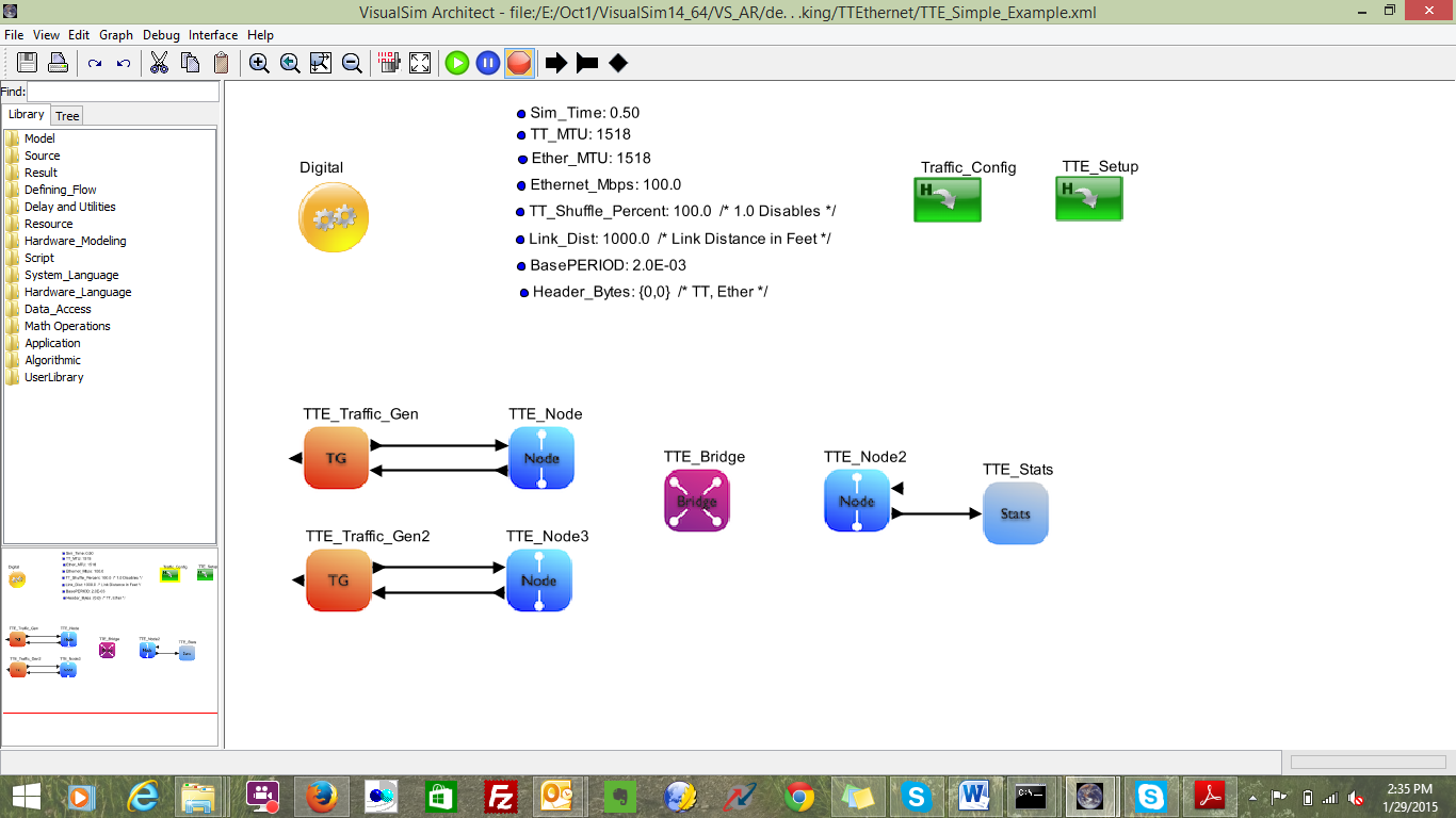
A demonstration system is provided with explanation on the use of this library. The block diagram is provided below:

Figure 1.0 Block Diagram of Simple TTEthernet Network

Node 1 and Node 2 are the synchronization masters, Node 5 acts as a Synchronization client and Bridge acts as a compression master in figure 1.0. Each Source node’s (Node1 & Node2) or Synchronization masters can generate messages of Time-Triggered (TT), Rate-Constrained (RC) or Best-Effort (Ethernet). Node 1 and Node 2 transmit messages to a single client Node5 which is connected by a Bridge in between.
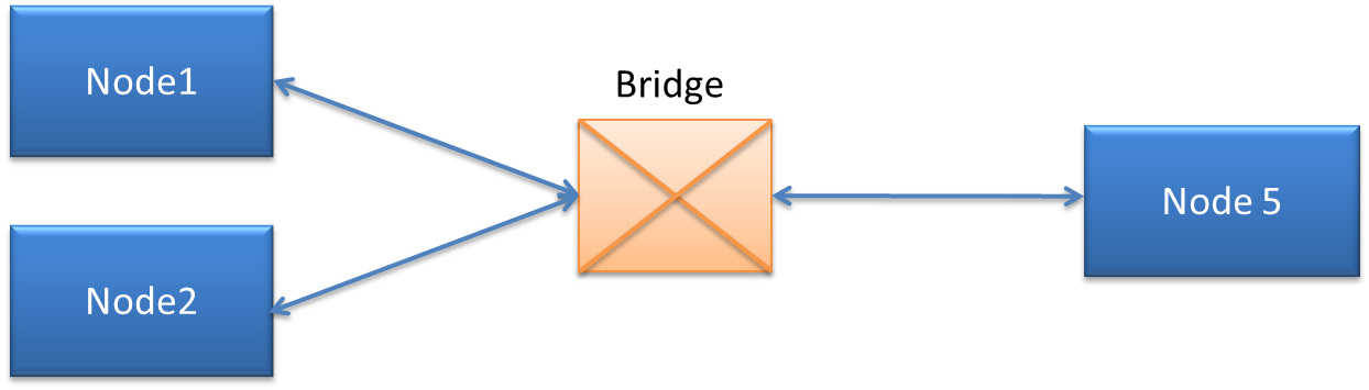
The VisualSim model of this design is at VS_AR/demo/networking/TTEthernet/TTE_Simple_Example.xml
Each node consists of one traffic generator which can generate messages of TT, RC and Ethernet; and a node block. The bridge uses the TTE_Bridge block. As Node_5 is a client, we have connected TTE_Stats to it to generate network statistics and stream latency. The TTE_Config_Table and TTE_Setup blocks are added to this block diagram editor to define network attributes. Users have to define few top level model parameters and are given below
Ethernet_Mbps = 100.0
Link_Dist = 1000.0 /* Link Distance in Feet, user can modify this */
BasePeriod = 2.0e-3
Header_Bytes={0,0}
TT_Shuffle_Percent = 100.0
Ethernet_MTU=1518
TT_MTU=1518
The Digital simulation is added with a stop time. When you run the simulation, there are four outputs. There are two plots- one displaying the latency for all the streams and the other is Histogram of the latency. There are two text files that are written at the end of the simulation- one contains information and warning messages, and the other contains the latency statistics for each stream.
 
Figure 2.0 VisualSim Model
Basic Rules
  1. All the Source and Destination node names must start with Node_ followed by a number
  2. All Bridges must start with Bridge_ followed by a number
  3. Each Traffic Generator will have a separate Traffic Table
  4. Bandwidth credit and Class type for all streams from all nodes are listed in a single Stream Table
  5. TTE_Setup block must be present in all models using TTEthernet libraries
  6. The TTE_Config_Table is only an example of the required Tables. The user must modify all the Tables to setup the required configuration. Additional Traffic Tables must be added to cover all the Nodes and need to make sure TT_Config_Table is configured correctly.
  7. Construction Steps
To construct an TTEthernet model, there are five steps
  1. TTE_Config_Table configuration
  2. Pre-Process block called TTE_Setup
  3. Instantiate Nodes and Bridges
  4. Add the traffic for each Nodes and define mode of message transmission.
  5. Attach Statistics block to each of the nodes that are receiving the data.
Step 1:

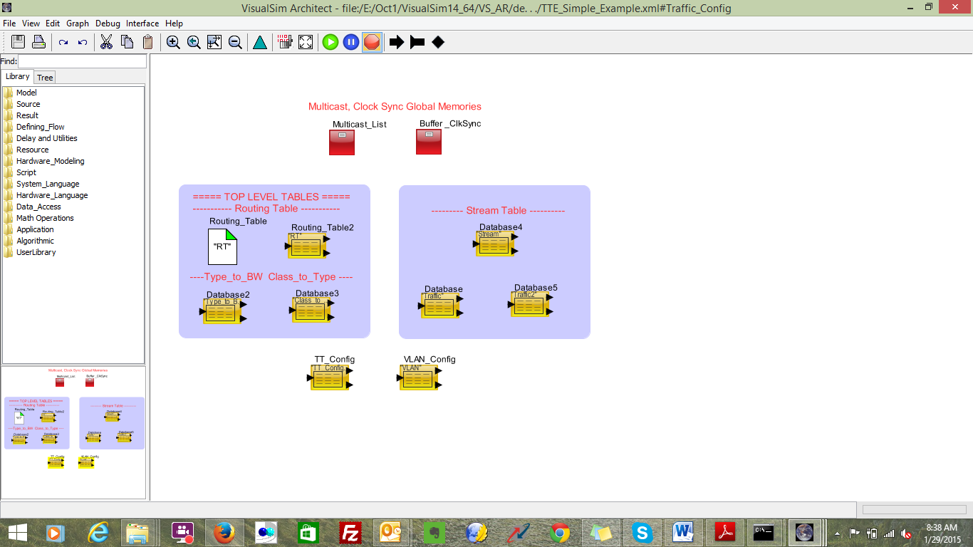
1. Drag Application->Networking->TTE->TTE_Config_Table into block diagram editor
This provides the list of sample Tables that are required for the TTEthernet model.

                               
Figure 3: TTE_Config_Tables
1.1 Roting_Table (RT): Configure based on your network requirements. This is required to handle the routing between nodes, compute latency on the links and maintain     statistics. For this tutorial configure RT as below
 
Figure 4: Routing Table Configuration
1.2 Buffer_ClkSync: No change required. Buffer_ClkSync is a Memory_Init block. This contains a set of required parameters for TTE. The following is the list of variables.

Percent_BW global 0.75 ; ---Maximum allocation to Class A or B of the total bandwidth for that Type
Default_ProcTime global 1.0E-06; Default Processing time for node processing.
Max_Buffer_Pkts      global   256 ; Maximum buffer packet size.
Max_Pkt_Bytes global 1500 ; ---Maximum packet size Max_Buffer_Pkts global 256 Maximum number of buffers at each Node. Each buffer can hold one Data Structure or packet
Grand_Master global "Node_1" ; ---Node Name of the Master for the Clock Sync. Grand_Master_Rate global 200.0E-03 ; ---Rate of Clock Synchronization messages from the Grand Master Node

1.3 Multicast_List: Please make sure that you have required source and destination names in the table
1.4 Traffic Table: One table is required for each Node. Enter the list of TT, RC and Ethernet streams. One sample table is provided. Copy this instance to generate the required number of traffic tables. Make sure to give each Table a unique Name for the Linking_Table_Name. The list of all the Traffic_Tables must be provided to the TTE_Setup block.
ID  Identifier     Task_Source   Task_Destination   Mbps         Task_Size        Start_Time  Stop_Time  Protocol VLAN Type ;       
 1  "TT1"            Node_1            Node_5                   TT_Mbps   TT_Bytes         3.0e-12         0.5                  UDP        1         7  ;
 2  "RC1"            Node_1           Node_5                    0.5             64                     1.5E-03          0.5                 UDP         2         6  ;
 3  "RC2"            Node_1           Node_5                    0.5             128                   2.0E-03          0.5                 UDP         3         6  ;
 4  "Ethernet"   Node_1           Node_5                    0.3              64                    2.5E-03          0.5                 UDP          4         5  ;  


ID: Increasing sequence number
Identifier: This determines the message stream type
Task_Source: Name of this Source Node.
Task_Destination: Name of the final destination or listener.
Mbps: Generation rate of this traffic stream
Task_Size: Packet data size. Does not include headers or tailers
Start_Time: Time in seconds after the start of the simulation
Stop_Time: Time in seconds after the start of the simulation
Protocol: UDP or TCP
VLAN: This is VLAN ID and it enables users to select BAG
Type: Type of Class. Can be 0 to 7.
1.5 Stream: This table contains the Class and the requested bandwidth for all TTEthernet stream from all the nodes.

ID       Mac_ID                              Identifier             SR_Class  Mbps  ;   
 1        "a0:36:9f:0c:77:38"        "TTE1"                    A              0.2  ;
 2        "a0:36:9f:0c:77:38"        "RC1"                      A             0.2  ;
 3        "a0:36:9f:0c:77:38"        "RC2"                     B               0.5  ;
 4        "a0:36:9f:0c:77:38"        "Ethernet"             A              0.3  ;
 5        "a0:36:9f:0c:77:39"         "TTE2"                   A             0.2  ;
 6       "a0:36:9f:0c:77:39"          "RC3"                    A              0.2  ;
 7        "a0:36:9f:0c:77:39"         "RC4"                     B            0.5  ;
 8        "a0:36:9f:0c:77:39"         "Ethernet"            A            0.3  ;
 9       "a0:36:9f:0c:77:3A"          "TTE3"                   A           0.2  ;
 10     "a0:36:9f:0c:77:3A"           "RC5"                  A             0.2  ;
 11     "a0:36:9f:0c:77:3A"          "RC6"                  B              0.5  ;
 12     "a0:36:9f:0c:77:3A"          "Ethernet"          A            0.3  ;

ID: Increasing sequence number
MAC_ID: Physical address of the Node
Identifier: Unique ID for each TTE stream. This must match the Identifier in the Traffic Table.
SR_Class: Stream Reservation class of this TTE stream- A or B.
Mbps: Requested bandwidth
1.5    Type_to_BW: For each Bridge and Node in the model, the amount of bandwidth allocated to each Type is specified in this Table. Top Level parameter Bandwidth_Mbps determines Ethernet Speed and is common for all nodes.
Sample Format is as below

ID Type  Node_1  Node_2  Node_3  Bridge_4  Bridge_5  Node_5   ;
 0    0   0.0     0.0     0.0     0.0       0.0       0.0     ; /* Background                  */
 1    1   0.0     0.0     0.0     0.0       0.0       0.0     ; /* Best Effort                 */
 2    2   0.0     0.0     0.0     0.0       0.0       0.0     ; /* Excellent Effort            */
 3    3   1.0     1.0     1.0     1.0       1.0       1.0     ; /* Video  50ms latency         */
 4    4   1.0     1.0     1.0     1.0       1.0       1.0     ; /* Critical Apps               */
 5    5  25.0    25.0    25.0    33.0      33.0      33.0     ; /* Video   2ms latency         */
 6    6  25.0    25.0    25.0    25.0      25.0      25.0     ; /* Internet Control            */
                7    7  40.0    40.0    40.0    40.0      40.0      40.0     ; /* Network Control, highest    */

ID: Increasing sequence number starting from 1.
Type: Type of Class. The values are 0 to 7
Node_1, Bridge_1...: Bandwidth allocation. The sum of all the rows of each column must not exceed the total bandwidth of the link.

Please make sure that you have included all the available nodes in the model

1.6 Class_to_Type- For each Bridge and Node in the model, the mapping of Type to Class and B.
Sample table is as shown below
ID     Class  Node_1  Node_2  Node_3  Bridge_4  Bridge_5  Node_5 ;
 0       A         4                 4             4               4              4               4    ; /* Background                  */
               1       B         3                 3             3                3              3               3    ; /* Best Effort                 */

ID: Increasing sequence number starting from 1
Class: A or B
Type: Type of Class. The values are 0 to 7. Common to all Nodes and Bridges in the model.

1.7 TT_Config_Table: TT_Config table provides the timing precision for Time-Triggered messages. StartTime is computed based on the task size and the Network Speed. User should enter details for the complete flow, for example if Source node is Node_1 and the destination is Node_5 then all the Nodes and bridges involved in communication flow should be defined in the table.

Sample TT_Config_Table is shown below
Node             TTName   StartTime   BasePeriod      ProcTime ;
"Node_1"       "TT1"      1.25E-03     BasePERIOD    ProcTIME ;
"Node_2"       "TT1"      2.0E-03       BasePERIOD     ProcTIME ;  
"Node_3"       "TT3"      3.0E-03       BasePERIOD     ProcTIME ;   
"Bridge_4"     "TT1"      2.5E-03       BasePERIOD     ProcTIME ;
"Bridge_4"     "TT2"      3.0E-03      BasePERIOD     ProcTIME ;
"Bridge_4"      "TT3"      3.5E-03      BasePERIOD     ProcTIME ;
"Bridge_5"      "TT1"      3.0E-03     BasePERIOD     ProcTIME ;
"Bridge_5"      "TT2"      3.5E-03     BasePERIOD     ProcTIME ;
"Bridge_5"      "TT3"      4.0E-03     BasePERIOD     ProcTIME ;
             "Node_5"          "TT1"      3.5E-03    BasePERIOD      ProcTIME ;


1.8 VLAN: No change is required. In this table based on the VLAN ID BAG is allocated. For the Rate Constrained traffic stream this table decides the allocated bandwidth for a given VLAN. User can have as many VLAN’s and associated with BAG and LMax time. Sample VLAN table is shown below;
ID VLAN  BAG          LMax  ;       
 1   1         1.0e-6        256   ;
 2   2         1.5e-6     512   ;
 3   3         2.0e-6       1024  ;
 4   4         2.0e-6       1024  ;
                5   5        2.0e-6        1024  ;

Step2

In this step we will add the blocks required for pre-processing the tables. This block must be added to all TTE models or models that use the TTE blocks. This block does require the existence of the Traffic tables, Routing Table, Link Setup table, Type_to_BW table, Class_to_Type, TT_Config_Table table and Multicast Memory_Init block.
a. Instantiate the Application->Networking->TTE->TTE_Setup block.
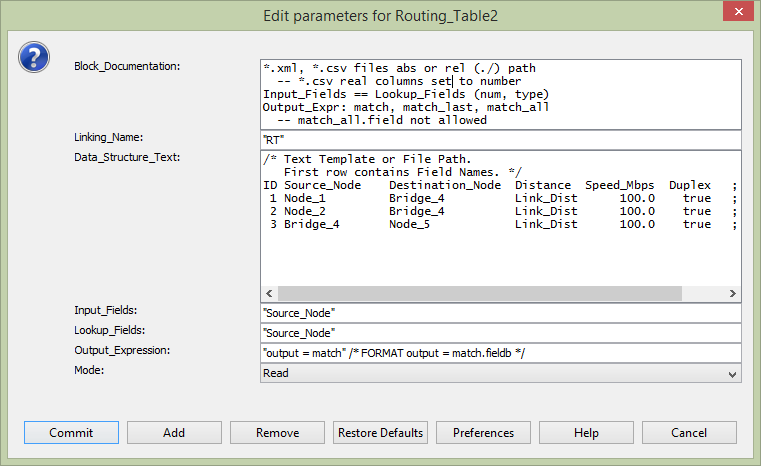
b. Link the Routing_Table_Name parameter to the top-level. This ensures that all blocks will use the same name.
c. In the parameter ‘Traffic_Tables’, list all the traffic tables names as strings in array.
Step3
Each transmitting node or synchronizing master node requires two blocks – TTE_Traffic_Gen and Node block. The assembly of the two blocks is as below
 
Figure 5: Assembly of Source Node

At the receiver side or client side only Node block is sufficient. To collect network activities and statistics one can connect TTE_Stats to the client node block. The assembly of the two blocks is as shown below
 
Figure 6: Assembly of Client Node/ Destination only node

Step4

The Bridge connects the Nodes to the network and also connects to other Bridges. The bridge block handles the Routing, broadcast of clock synchronization. A model can have a single bridge with all the Nodes connected to it.
 
Figure 7 Single Bridge Network

If a model has multiple bridges, instantiate as many TTE_Bridge blocks and update the Link_Setup. The topology of the network is determined by the Link_Setup table. The Block Diagram shows the number of Bridge and Node instances.

 
Figure8 Multiple Bridge Network

The following is the sequence:
a. Add as many Application->Networking->TTE->TTE_Bridge blocks as you have defined in the Link Configuration table
b. Assign a unique name to each Bridge block. The rule here is that the name must be Bridge_ followed by a number. No two Bridges can have the same
c. For the parameter, add the Routing_Table_Name. For now it is just “RT”.

Step5
The TTE_Stats block can be connected directly to the Node out for a Destination-only or the data_out port of the TT_Traffic_Gen block for a Source+Destination block.
The TTE_Stats generates 3different pieces of information. They are:

1. The latency statistics and through for all the streams arriving at Node to which this TTE_Stats is connected.

Time-Triggered

Rate Constraint

N1_to_N5_TT1_1

Latency

                Minimum: 2.5061367090 ms

                Mean:  2.5061367090 ms

                Std Dev: 29.1 ps

                Maximum: 2.5061367090 ms

Throughput

                                Mbps:   0.0328661952051

N2_to_N5_RC2_3

Latency

                Minimum: 24.5134240 us

                Mean: 494.2624945 us

                Std Dev: 571.1953459 us

                Maximum: 2.0779767120 ms

Throughput

                              Mbps:     0.5011401721222

Ethernet

N1_to_N5_Ether_4

Latency

                                     Minimum:      14.2734240 us

                               Mean:    519.6828018 us

                                      Std Dev:         617.3499543 us

                                       Maximum:   2.8099000580 ms

                                                            Throughput

                                              Mbps:     0.3010222764019
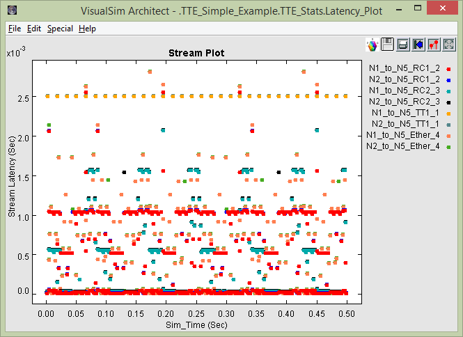


Here
N1_to_N5- Node_1 to Node_5
TT_1- Time Triggered stream with ID 1 in the Traffic Table
RC2_3- Rate Constrained  stream with ID 3 in the Traffic Table
Ether_4- Ethernet stream with ID 4 in the Traffic Table
Minimum- Lowest latency recorded during the simulation
Maximum- Highest latency recorded during the simulation
Mean- Average of all the latencies recorded
Std Dev- Standard Deviation of the latencies

2.    Graphical plot showing the Latency for all the streams arriving at the Node to which this TTE_Stats block is connected.
 

Figure 9: Stream Latency Plot


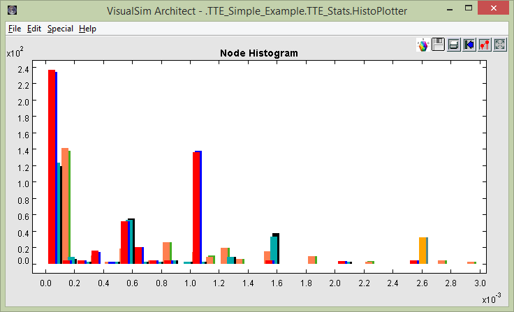
3.    Histogram of the Latency for all the streams arriving at the Node to which this TTE_Stats block is connected.
 
Figure 10 Histogram Latency plot

The following is the connection sequence:
a. Connect an Application->Networking->TTE->TTE_Stats block to the output of each of the Nodes. This will capture all the statistics including the activity traces, latency and histogram plots. You can see a unique latency graph at each Listener of Destination Node. We only need this block for Nodes that will receive data.
b. Enter the name of the Node that this block is connected.

Step6

Now the model has been constructed. The next step is to run the simulation. Each simulation run can have different setup values- such as Network Toplogy (Link_Setup file), traffic streams from each node (Traffic table), number of TT/RC/Ethernet streams (stream table) and allocation of bandwidth to each Type at each Bridge (Type_to_BW).
For each run, the statistics are provided in a combination of files and graphical plots. View Step 6 to see the list of plots and reports.


Advanced Tutorial

1.TTEthernet model with 8 Source Nodes
Let us make use of TTEthernet_Simple_Example.xml model to extend the system with additional 6 Nodes or total of 8 Nodes.
Step1:
Extending System with additional Nodes and configure TTE_Config_Table
  1. Instantiate additional TT_Node’s and provide unique name. Connect TT_Traffic_Gen blocks for each TT_Node’s and provide unique name.
  2. Open TT_Config_Table block, create additional Traffic_Table’s for all Source Nodes.
  3. Update Routing Table (RT) with additional node details
  4. Update additional node details to Type_to_BW and Class_to_Type blocks.
  5. Update TT_Config table with updated Traffic_Table details (TT1, TT2, TT3…) and timing precision based on the network speed and task size.
  6. VLAN Table – No modification is required
  7.  Stream Table – No modifications required
Step2:
TTE_Setup
1.Update Traffic_Tables parameter with all additional Traffic_Table’s names

Step3:
Run Simulation


2.  TTEthernet Model with 8 nodes and 3 Destination Nodes
In this tutorial we shall extend the model developed in advanced tutorial part 1.
Step1:
Open the model developed in Part-1 and instantiate additional destination nodes and TTE_Stats blocks. Provide unique names for TTE destination nodes.
Step2:
Open TTE_Config_Table block and update Routing Table(RT), Type_to_BW, Class_to_Type, TT_Config and Traffic Table. With Regards to Traffic table, user can decide which is the Destination node should be selected.
Step3:
Run Simulation

Note: Final version of the model is available in VS_AR\doc\Training_Material\Tutorial\WebHelp\Tutorial\Networking\TTE_8_Nodes_3dest_Nodes.xml

3. TTEthernet Model with 8 Nodes, 2 Bridges and 3 Destination Nodes
In this tutorial we shall extend the model developed in advanced tutorial Part2.
Step1:
Open the model developed in Part-1 and instantiate additional 1 TTE_Bridge block. Provide unique name.
Step2:
Open TTE_Config_Table block and update Routing Table(RT), Type_to_BW, Class_to_Type, TT_Config and Traffic Table. In the RT table one can select the flow,  sample RT table is shown below
ID Source_Node    Destination_Node  Distance  Speed_Mbps  Duplex   ;       
 1 Node_1         Bridge_4          Link_Dist      100.0    true   ;
 2 Node_2         Bridge_5          Link_Dist      100.0    true   ;
 3 Node_3         Bridge_4          Link_Dist      100.0    true   ;  
 4 Node_4         Bridge_5          Link_Dist      100.0    true   ;  
 5 Node_5         Bridge_4          Link_Dist      100.0    true   ;  
 6 Node_6         Bridge_5          Link_Dist      100.0    true   ;  
 7 Node_7         Bridge_4          Link_Dist      100.0    true   ;  
 8 Node_8         Bridge_4          Link_Dist      100.0    true   ;      
 9 Bridge_4       Node_10           Link_Dist      100.0    true   ;
 10 Bridge_5      Node_10        Link_Dist      100.0    true   ;
 11 Bridge_5      Node_11        Link_Dist      100.0    true   ;
 12 Bridge_4      Node_12           Link_Dist      100.0    true   ;
Step3:
Run Simulation
Note: Final version of the model is available in VS_AR\doc\Training_Material\Tutorial\WebHelp\Tutorial\Networking\TTE_8_Nodes_3dest_Nodes_2Bridge.xml