Problem statement
The powertrain constitutes the most important module in a car. It controls the other sub-systems in the car and hence can be called the brain of the car. Engine Control Unit (ECU) is one of two units in the Powertrain Control Module (PCM) and ECU is responsible for the optimal performance of the engine. The other unit, the Transmission Control Unit (TCU) interacts with the engine sensors and ensures fuel efficiency. Thus, the PCM is the focal point for all the sensors in the car and it has to function optimally without failure to ensure the smooth functioning of the car.

Performance and Power optimization prior to the development
Model construction
We created a model to gauge the power consumed by the different components of the PCM. The model comprised four mechanical devices – Engine, Generator, Transmission, Final Drive – four parts – Headlights, Radio, Radar and ECU. The data from various units go into the execution unit.
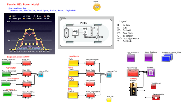
The Power_Generator module generated the packets for the mechanical devices. The module acts as a power generation and battery charging unit. The module increases the battery charge based on a specified sequence. The value, ‘StartTime’ specifies the start of the power generation. The Power Manager table is updated every ‘Charge_Update_Interval’ with the charge increment. The charge can be enabled and disabled using the ‘ChargeEnable’ parameter. All units are in Watts. All these parameters are configurable by the user.
The execution unit has the following four types of tasks:
- Multiple (up to 4) inputs arrive to fire the block
- Inputs plus clock enable
- Clock Enable
- Interrupt-driven which will be a higher priority
The tasks are mapped to a resource with the help of mapper modules. The mapping information are obtained from the databases. Following are the two databases used for mapping:
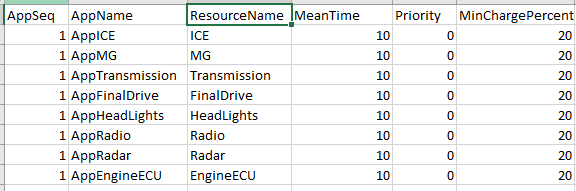
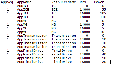
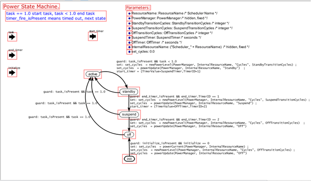
The resources are modelled with the help of a dynamic instantiation module. Hence, the expansion of resource list can be performed by configuring the parameters. Finite State Machines are also used in the model to simulate accurate power usage. The following graphic shows how power FSM has been modelled:
Types of analysis
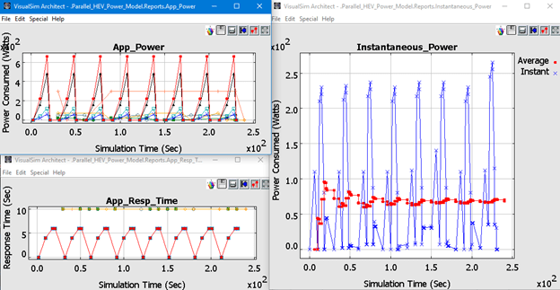
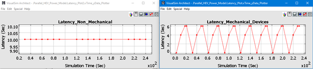
As part of the analysis, we calculated latency plots for tasks that complete their execution. The following are the latency plots which were obtained:
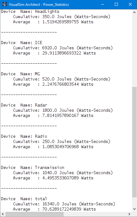
We arrived at the power consumed by different devices.
Cumulative and average power consumed per devices is listed here: